Dell Alienware x16 R1 Service Manual
Dell Alienware x16 R1 Manual
 |
View all Dell Alienware x16 R1 manuals
Add to My Manuals
Save this manual to your list of manuals |
Dell Alienware x16 R1 manual content summary:
- Dell Alienware x16 R1 | Service Manual - Page 1
Alienware x16 R1 Service Manual Regulatory Model: P120F Regulatory Type: P120F001/P120F003 January 2023 Rev. A00 - Dell Alienware x16 R1 | Service Manual - Page 2
use of your product. CAUTION: A CAUTION indicates either potential damage to hardware or loss of data and tells you how to avoid the problem. WARNING: A WARNING indicates a potential for property damage, personal injury, or death. © 2023 Dell Inc. or its subsidiaries. All rights reserved. Dell - Dell Alienware x16 R1 | Service Manual - Page 3
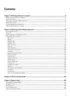
...5 Safety instructions...5 Electrostatic discharge-ESD protection...6 ESD field service kit ...6 Transporting sensitive components...7 After working inside your computer...7 Chapter 2: Removing and installing components 8 Recommended tools...8 Screw list...8 Major components of Alienware x16 R1 - Dell Alienware x16 R1 | Service Manual - Page 4
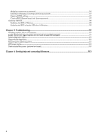
BIOS in Windows...98 Updating the BIOS using the USB drive in Windows 98 Chapter 5: Troubleshooting...99 Handling swollen Lithium-ion batteries...99 Locate the Service Tag or Express Service Code of your Dell computer 99 System-diagnostic lights...99 SupportAssist diagnostics...100 Recovering the - Dell Alienware x16 R1 | Service Manual - Page 5
and the contacts. CAUTION: You should only perform troubleshooting and repairs as authorized or directed by the Dell technical assistance team. Damage due to servicing that is not authorized by Dell is not covered by your warranty. See the safety instructions that is shipped with the product or at - Dell Alienware x16 R1 | Service Manual - Page 6
may not be obvious, such as intermittent problems or a shortened product life span. As more difficult type of damage to recognize and troubleshoot is the intermittent (also called latent or and the hardware is known as bonding. Use only Field Service kits with a wrist strap, mat, and bonding wire. - Dell Alienware x16 R1 | Service Manual - Page 7
plastic heat sink casings, away from internal parts that are insulators and often highly charged. ● Working Environment - Before deploying the ESD Field Service kit, assess the situation at the customer location. For example, deploying the kit for a server environment is different than for a desktop - Dell Alienware x16 R1 | Service Manual - Page 8
Removing and installing components NOTE: The images in this document may differ from your computer depending on the configuration you ordered. Recommended tools The procedures in this document may require the following tools: ● Phillips screwdriver #0 ● Plastic scribe Screw list NOTE: When - Dell Alienware x16 R1 | Service Manual - Page 9
heat-sink assembly System board M2x3 8 I/O-board Palm-rest and keyboard M2x2.5 4 assembly Power button Palm-rest and keyboard M1.2x2 2 assembly Major components of Alienware x16 R1 The following image shows the major components of - Dell Alienware x16 R1 | Service Manual - Page 10
1. Rear I/O-cover 2. Base cover 3. M.2 2330 solid-state drive 4. M.2 2230 solid-state drive thermal shield 5. Solid-state drive mounting bracket 6. Wireless-card bracket 7. Solid-state drive bracket 8. USB Type-C bracket 9. Wireless card 10. Fan and heat-sink assembly 11. Graphics-card fan 12. - Dell Alienware x16 R1 | Service Manual - Page 11
14. Palm-rest and keyboard assembly 15. Speakers 16. Speaker cable 17. Touchpad 18. Power-adapter port 19. Antenna 20.Display assembly 21. Processor fan 22.Headset port 23.Display-cable holder 24.Display-cable bracket 25.Battery 26.I/O board 27.M.2 2280 solid-state drive 28.M.2 2280 solid-state - Dell Alienware x16 R1 | Service Manual - Page 12
12 - Dell Alienware x16 R1 | Service Manual - Page 13
Steps 1. Remove the two screws (M2.5x5) that secure the base cover to the palm-rest and keyboard assembly. 2. Loosen the four captive screws (M2.5x5) that secure the base cover to the palm-rest and keyboard assembly. 3. Using a plastic scribe, pry the base cover from the gap created after loosening - Dell Alienware x16 R1 | Service Manual - Page 14
4. Lift the base cover by holding it in the center at the bottom and slide the base cover off the palm-rest and keyboard assembly. 5. Disconnect the battery cable from the system board. 6. Press and hold the power button for 20 seconds to ground the computer and drain the flea power. Installing the - Dell Alienware x16 R1 | Service Manual - Page 15
15 - Dell Alienware x16 R1 | Service Manual - Page 16
kind to pry on or against the battery. ● Ensure any screws during the servicing of this product are not lost or misplaced, to prevent accidental puncture or damage can be dangerous. In such an instance, contact Dell technical support for assistance. See www.dell.com/contactdell. ● Always purchase - Dell Alienware x16 R1 | Service Manual - Page 17
Steps 1. Disconnect the battery cable from the system board (if not disconnected earlier). 2. Peel the tape that secures the battery cable to the battery. 3. Remove the four screws (M2x4) that secure the battery to the palm-rest and keyboard assembly. 4. Lift the battery off the palm-rest and - Dell Alienware x16 R1 | Service Manual - Page 18
Steps 1. Using the alignment posts, place the battery on the palm-rest and keyboard assembly. 2. Align the screw holes on the battery with the screw holes on the palm-rest and keyboard assembly. 3. Replace the four screws (M2x4) that secure the battery to the palm-rest and keyboard assembly. 4. - Dell Alienware x16 R1 | Service Manual - Page 19
kind to pry on or against the battery. ● Ensure any screws during the servicing of this product are not lost or misplaced, to prevent accidental puncture or damage can be dangerous. In such an instance, contact Dell technical support for assistance. See www.dell.com/contactdell. ● Always purchase - Dell Alienware x16 R1 | Service Manual - Page 20
Steps 1. Turn the battery over and peel the battery cable from the battery. 2. Disconnect the battery cable from the connector on the battery. 3. Lift the battery cable off the battery. Installing the battery cable Prerequisites If you are replacing a component, remove the existing component before - Dell Alienware x16 R1 | Service Manual - Page 21
Steps 1. Align and adhere the battery cable to the battery. 2. Connect the battery cable to the connector on the battery. Next steps 1. Install the battery. 2. Install the base cover. 3. Follow the procedure in After working on your computer. Wireless card Removing the wireless card Prerequisites 1. - Dell Alienware x16 R1 | Service Manual - Page 22
About this task The following image(s) indicate the location of the wireless card and provides a visual representation of the removal procedure. 22 - Dell Alienware x16 R1 | Service Manual - Page 23
Steps 1. Remove the two screws (M2x4) that secures the thermal shield to the wireless card and palm-rest and keyboard assembly. NOTE: The thermal shield is applicable for computers shipped with certain configurations only. 2. Lift the wireless card thermal shield off the palm-rest and keyboard - Dell Alienware x16 R1 | Service Manual - Page 24
24 - Dell Alienware x16 R1 | Service Manual - Page 25
the antenna cables to the wireless card. The following table provides the antenna-cable color scheme for the wireless card that is supported by your computer. Table 2. Antenna-cable color scheme Connectors on the wireless card Main Antenna-cable color Silkscreen marking White MAIN △ (white - Dell Alienware x16 R1 | Service Manual - Page 26
2. Remove the base cover. About this task The following image(s) indicate the location of the rear I/O-cover and provides a visual representation of the removal procedure. NOTE: To prevent damaging your computer, ensure that the Tron-light cable has been disconnected from the system board before - Dell Alienware x16 R1 | Service Manual - Page 27
About this task The following image(s) indicate the location of the rear I/O-cover and provides a visual representation of the installation procedure. NOTE: To avoid damaging your computer, ensure that the Tron-light cable is not pinched when sliding the rear I/O-cover into palm-rest and keyboard - Dell Alienware x16 R1 | Service Manual - Page 28
keyboard assembly. 2. Peel the tape that secures the antenna cables to the palm-rest and keyboard assembly. 3. Remove the antenna cables from the routing guides on the palm-rest and keyboard assembly. 4. Lift the left and right antennas, along with the antenna cables, off the palm-rest and keyboard - Dell Alienware x16 R1 | Service Manual - Page 29
on the palm-rest and keyboard assembly. 2. Route the antenna cables onto the routing guides on the palm-rest and keyboard assembly. 3. Adhere the tape that secures the antenna depend on the configuration ordered. Supported card configurations: ● M.2 2230 solid-state drive + 2230 mounting bracket 29 - Dell Alienware x16 R1 | Service Manual - Page 30
● M.2 2280 solid-state drive The following image(s) indicate the location of the M.2 2230 solid-state drive in SSD-2 and provides a visual representation of the removal procedure. Steps 1. Remove the screw (M2x4) that secures the solid-state drive thermal shield to the solid-state drive and palm- - Dell Alienware x16 R1 | Service Manual - Page 31
computer has two solid-state drive slots (SSD-1 and SSD-2). The M.2 card installed on M.2 slot will depend on the configuration ordered. Supported card configurations: ● M.2 2230 solid-state drive + 2230 mounting bracket ● M.2 2280 solid-state drive The following image(s) indicate the location of - Dell Alienware x16 R1 | Service Manual - Page 32
computer has two solid-state drive slots (SSD-1 and SSD-2). The M.2 card installed on M.2 slot will depend on the configuration ordered. Supported card configurations: ● M.2 2230 solid-state drive + 2230 mounting bracket ● M.2 2280 solid-state drive The following image(s) indicate the location of - Dell Alienware x16 R1 | Service Manual - Page 33
following procedure applies only to computers shipped with an M.2 2280 solid-state drive. NOTE: The M.2 card installed on M.2 slot will depend on the configuration ordered. Supported card configurations: 33 - Dell Alienware x16 R1 | Service Manual - Page 34
● M.2 2230 solid-state drive + 2230 mounting bracket ● M.2 2280 solid-state drive The following image(s) indicate the location of the M.2 2280 solid-state drive in SSD-1 and provides a visual representation of the installation procedure. Steps 1. Align the notch on the solid-state drive with the tab - Dell Alienware x16 R1 | Service Manual - Page 35
Solid-state drive bracket Removing the solid-state drive bracket Prerequisites 1. Follow the procedure in Before working inside your computer. 2. Remove the base cover. 3. Remove the 2230 solid-state drive or 2280 solid-state drive, as applicable. About this task The following image(s) indicate the - Dell Alienware x16 R1 | Service Manual - Page 36
Steps 1. Align the screw hole on the solid-state drive bracket with the screw hole on the palm-rest and keyboard assembly. 2. Replace the screw (M2x4) that secures the solid-state drive bracket to the palm-rest and keyboard assembly. Next steps 1. Install the 2230 solid-state drive or 2280 solid- - Dell Alienware x16 R1 | Service Manual - Page 37
37 - Dell Alienware x16 R1 | Service Manual - Page 38
Steps 1. Remove the two speakers off the palm-rest and keyboard assembly. 2. Peel the Mylar and lift the Mylar off the keyboard-controller board. 3. Open the latch and disconnect the keyboard-controller board cable from keyboard-controller board. 4. Fold up the keyboard-controller board cable. 5. - Dell Alienware x16 R1 | Service Manual - Page 39
39 - Dell Alienware x16 R1 | Service Manual - Page 40
Steps 1. Align and place the touchpad into the slot on the palm-rest and keyboard assembly. NOTE: Turn the computer over and open the display. Ensure that the touchpad is equally aligned along all four sides. 2. Replace the nine screws (M1.6x1.8) that secure the touchpad to the palm-rest and - Dell Alienware x16 R1 | Service Manual - Page 41
Keyboard-controller board Removing the keyboard-controller board Prerequisites 1. Follow the procedure in Before working inside your computer. 2. Remove the base cover. 3. Remove the battery. About this task The following image(s) indicate the location of the keyboard-controller board and provides a - Dell Alienware x16 R1 | Service Manual - Page 42
Steps 1. Lift the Mylar that secures the keyboard-controller board to the palm-rest and keyboard assembly. 2. Open the latch and disconnect the keyboard-backlight cable from the keyboard-controller board. 3. Open the latch and disconnect the touchpad-light cable from the keyboard-controller board. - Dell Alienware x16 R1 | Service Manual - Page 43
Steps 1. Using the alignment posts, place the keyboard-controller board into the slot on the palm-rest and keyboard assembly. 2. Replace the two screws (M1.6x1.6) that secure the keyboard-controller board to the palm-rest and keyboard assembly. 3. Slide the keyboard cable into the connector on the - Dell Alienware x16 R1 | Service Manual - Page 44
Next steps 1. Install the battery. 2. Install the base cover. 3. Follow the procedure in After working inside your computer. Display assembly Removing the display assembly Prerequisites 1. Follow the procedure in Before working inside your computer. 2. Remove the base cover. 3. Remove the rear I/O- - Dell Alienware x16 R1 | Service Manual - Page 45
45 - Dell Alienware x16 R1 | Service Manual - Page 46
Steps 1. Remove the four screws (M2.5x4) that secure the left and right display hinge to the bottom side of the palm-rest and keyboard assembly. 2. Remove the two screws (M2x2.5) that secures the display-cable bracket to the palm-rest and keyboard assembly. 3. Lift the display-cable bracket off the - Dell Alienware x16 R1 | Service Manual - Page 47
13. Remove the four screws (M2.5x4) that secure the left and right display hinge to the top side of the palm-rest and keyboard assembly. 14. Lift the display assembly off the palm-rest and keyboard assembly. 15. After performing the steps above, you are left with the display assembly. Installing the - Dell Alienware x16 R1 | Service Manual - Page 48
48 - Dell Alienware x16 R1 | Service Manual - Page 49
49 - Dell Alienware x16 R1 | Service Manual - Page 50
NOTE: Place the computer on a soft and clean surface to avoid scratching the display. Steps 1. Align the screw holes on the display assembly with the screw holes on the palm-rest and keyboard assembly. 2. Gently slide the display cable through the plastic strip between the palm-rest and keyboard - Dell Alienware x16 R1 | Service Manual - Page 51
10. Replace the screw (M1.6x3) that secures the microSD-card reader to the display-cable holder. 11. Route the display cable through the opening on the rear side of the palm-rest and keyboard assembly. 12. Rotate the display-cable holder to 180 degrees so that the microSD card-reader aligns with the - Dell Alienware x16 R1 | Service Manual - Page 52
Steps 1. Disconnect the processor-fan cable and speaker cable from the system board. 2. Remove the speaker cable and the antenna cables through the routing guides on the bottom of the processor fan. 3. Remove the two screws (M2x4) that secure the processor fan to the palm-rest and keyboard assembly. - Dell Alienware x16 R1 | Service Manual - Page 53
the removal procedure. Steps 1. Disconnect the graphics-card fan cable from the system board. 2. Remove the speaker cable and antenna cables from the routing guides on the bottom of the graphics-card fan. 3. Remove the two screws (M2x4) that secure the graphics-card fan to the palm-rest and keyboard - Dell Alienware x16 R1 | Service Manual - Page 54
. 4. Route the speaker cable and the antenna cable through the routing guides on the bottom of the graphics-card fan. Next steps 1. Install the installing this component, please refer to the techsheet bundled with the service kit. This is only applicable for computers with the following Graphics - Dell Alienware x16 R1 | Service Manual - Page 55
The following image indicates the connectors on your system board. 1. Right tron-light cable 3. Power-adapter port cable 5. Battery cable 7. Solid-state drive slot 1 (SSD-1) 9. Left tron-light cable 11. Processor fan 13. Power-button cable 15. I/O-board cable 17. Display cable 2. Right fan cable - Dell Alienware x16 R1 | Service Manual - Page 56
56 - Dell Alienware x16 R1 | Service Manual - Page 57
port cable to the system board. 9. Open the latch and disconnect the headset port cable from the system board and remove it from the routing guides on the fan and heat-sink assembly. 10. Disconnect the speaker cable from the system board. 11. Open the latch and disconnect the keyboard-controller - Dell Alienware x16 R1 | Service Manual - Page 58
and ensure that it covers the entire surface of it. CAUTION: Once the system board assembly has been removed from the computer, follow the instructions in the tech sheet dispatched with the replacement system board assembly. CAUTION: Do not use an alcohol wipe to clean the Element 31 thermal grease - Dell Alienware x16 R1 | Service Manual - Page 59
About this task NOTE: When installing this component, please refer to the techsheet bundled with the service kit. This is only applicable for computers with the following Graphics Processing Unit (GPU) configurations that have Element 31 grease is applied to the CPU. ● - Dell Alienware x16 R1 | Service Manual - Page 60
60 - Dell Alienware x16 R1 | Service Manual - Page 61
Steps 1. Turn the system board over. 2. Align the screw hole on the USB Type-C bracket with the screw hole on the system board. 3. Replace the screw (M2x3) that secures the USB Type-C bracket to the system board. 4. Install the fan and heat-sink assembly. 5. Turn the system-board assembly over and - Dell Alienware x16 R1 | Service Manual - Page 62
and close the latch to secure the cable and route it through the routing guides on the fan and heat-sink assembly. 13. Adhere the tape that secures the headset port cable to the system board and route it through the routing guides on the fan and heat-sink assembly. 16. Connect the right fan cable - Dell Alienware x16 R1 | Service Manual - Page 63
Steps 1. Remove the two screws (M2x2.5) that secure the power-adapter port bracket to the palm-rest and keyboard assembly. 2. Lift the power-adapter port bracket off the palm-rest and keyboard assembly. 3. Using pull tab, disconnect the power-adapter port cable from the system board. 4. Peel the - Dell Alienware x16 R1 | Service Manual - Page 64
. 3. Adhere the tape that secures the power-adapter port to the fan and heat-sink assembly. 4. Route the power-adapter port cable through the routing guides on the fan and heat-sink assembly. 5. Place the power-adapter port bracket on the power-adapter port. 6. Align the screw holes on the power - Dell Alienware x16 R1 | Service Manual - Page 65
Steps 1. Disconnect the microSD-card reader cable from the system board. 2. Peel the tape that secures the headset-port cable to the system board. 3. Open the latch and disconnect the headset-port cable from the system board. 4. Peel the tape that secures the headset-port cable to the fan and heat- - Dell Alienware x16 R1 | Service Manual - Page 66
Steps 1. Align and place the headset port into the slot on the palm-rest and keyboard assembly. 2. Replace the screw (M1.6x3) that secures the headset port to the palm-rest and keyboard assembly. 3. Adhere the tape that secures the headset-port cable to the fan and heat-sink assembly. 4. Connect the - Dell Alienware x16 R1 | Service Manual - Page 67
Steps 1. Remove the two screws (M2x2.5) that secures the display-cable bracket to the palm-rest and keyboard assembly. 2. Lift the display-cable bracket off the palm-rest and keyboard assembly. 3. Disconnect the microSD-card reader cable from the system board. 4. Disconnect the display cable from - Dell Alienware x16 R1 | Service Manual - Page 68
Installing the microSD-card reader Prerequisites If you are replacing a component, remove the existing component before performing the installation process. About this task The following image(s) indicate the location of the microSD-card reader and provides a visual representation of the - Dell Alienware x16 R1 | Service Manual - Page 69
Steps 1. Align the screw hole on the microSD card-reader along with the screw hole on the display-cable holder. 2. Replace the screw (M1.6x3) that secure the microSD-card reader to the display-cable holder. 3. Rotate the display-cable holder to 180 degrees so that the microSD card-reader aligns with - Dell Alienware x16 R1 | Service Manual - Page 70
Steps 1. Peel the tape that secures the speaker cable to the palm-rest and keyboard assembly. 2. Remove the speaker cables from the routing guides on the palm-rest and keyboard assembly. 3. Lift the right and left speakers, along with its cable, off the palm-rest and keyboard assembly. Installing - Dell Alienware x16 R1 | Service Manual - Page 71
posts, place the left and right speakers into their slots on the palm-rest and keyboard assembly. 2. Route the speaker cable through the routing guides on the palm-rest and keyboard assembly. 3. Adhere the tape that secures the speaker cable to the palm-rest and keyboard assembly. Next steps - Dell Alienware x16 R1 | Service Manual - Page 72
between the system board and heat sink. About this task NOTE: When installing this component, please refer to the techsheet bundled with the service kit. This is only applicable for computers with the following Graphics Processing Unit (GPU) configurations that have Element 31 grease is applied to - Dell Alienware x16 R1 | Service Manual - Page 73
Steps 1. Disconnect the left and right fan cables from the system board. 2. Turn the system-board assembly over. 3. In the reverse sequential order (8>7>6>5>4>3>2>1), remove the eight screws (M2x3) that secure the fan and heat-sink assembly to the system board. 4. Lift the fan and heat-sink assembly - Dell Alienware x16 R1 | Service Manual - Page 74
before performing the installation process. About this task NOTE: When installing this component, please refer to the techsheet bundled with the service kit. This is only applicable for computers with the following Graphics Processing Unit (GPU) configurations that have Element 31 grease is - Dell Alienware x16 R1 | Service Manual - Page 75
Steps 1. CAUTION: Do not use an alcohol wipe to clean the Element 31 thermal grease off the surface of the CPU or GPU, the alcohol solution from the wipes will dissolve the Element 31 grease into conductive metal particles. If these conductive metal particles come into contact with the surface of - Dell Alienware x16 R1 | Service Manual - Page 76
Next steps 1. Follow the procedure from step 5 to step 22 in Replacing the system board. NOTE: The system board can be removed and installed along with the heat sink. This simplifies the removal and installation procedure and avoids breaking the thermal bond between the system board and heat sink. - Dell Alienware x16 R1 | Service Manual - Page 77
Steps 1. Remove the four screws (M2x2.5) that secure the I/O board to the palm-rest and keyboard assembly. 2. Remove the tape that secures the IO daughter board cable to the palm-rest and keyboard assembly. 3. Disconnect and remove the IO daughter board cable from the IO daughter board. 4. Lift the - Dell Alienware x16 R1 | Service Manual - Page 78
Steps 1. Align the screw holes on the I/O board with the screw holes on the palm-rest and keyboard assembly. 2. Replace the four screws (M2x2.5) that secure the I/O board to the palm-rest and keyboard assembly. 3. Connect and remove the IO daughter board cable from the IO daughter board. 4. Adhere - Dell Alienware x16 R1 | Service Manual - Page 79
11. Follow the procedure in After working inside your computer. Power button Removing the power button Prerequisites 1. Follow the procedure in Before working inside your computer. 2. Remove the base cover. 3. Remove the battery. 4. Remove the 2230 solid-state drive or 2280 solid-state drive, as - Dell Alienware x16 R1 | Service Manual - Page 80
Installing the power button Prerequisites If you are replacing a component, remove the existing component before performing the installation process. About this task The following image(s) indicate the location of the power button and provides a visual representation of the installation procedure. - Dell Alienware x16 R1 | Service Manual - Page 81
Palm-rest and keyboard assembly Removing the palm-rest and keyboard assembly Prerequisites 1. Follow the procedure in Before working inside your computer. 2. Remove the base cover. 3. Remove the battery. 4. Remove the wireless card. 5. Remove the 2230 solid-state drive or 2280 solid-state drive, as - Dell Alienware x16 R1 | Service Manual - Page 82
Installing the palm-rest and keyboard assembly Prerequisites If you are replacing a component, remove the existing component before performing the installation process. Steps To install the palm-rest and keyboard assembly, perform the post-requisites. NOTE: The replacement palm-rest and keyboard - Dell Alienware x16 R1 | Service Manual - Page 83
18. Follow the procedure in After working inside your computer. 83 - Dell Alienware x16 R1 | Service Manual - Page 84
Drivers and downloads When troubleshooting, downloading or installing drivers it is recommended that you read the Dell Knowledge Based article, Drivers and Downloads FAQ 000123347. 84 - Dell Alienware x16 R1 | Service Manual - Page 85
System setup CAUTION: Unless you are an expert computer user, do not change the settings in the BIOS Setup program. Certain changes can make your computer work incorrectly. NOTE: Before you change BIOS Setup program, it is recommended that you write down the BIOS Setup program screen information - Dell Alienware x16 R1 | Service Manual - Page 86
or may not be displayed. Table 3. System setup options-System information menu Overview BIOS Version Displays the BIOS version number. Service Tag Displays the Service Tag of the computer. Asset Tag Displays the Asset Tag of the computer. Manufacture Date Displays the manufacture date of - Dell Alienware x16 R1 | Service Manual - Page 87
Table 3. System setup options-System information menu (continued) Overview Video Controller Displays the integrate graphics information of the computer. Video Memory Displays the video memory information of the computer. Wi-Fi Device Displays the Wi-Fi device installed in the computer. - Dell Alienware x16 R1 | Service Manual - Page 88
USB Ports Enables or disables all external USB ports in an OS environment. By default, Enable External USB Ports is selected. Enable USB Boot Support Enables or disables booting from USB mass storage devices such as external hard drive, optical drive, and USB drive. By default, Enable USB Boot - Dell Alienware x16 R1 | Service Manual - Page 89
discrete graphics controller will drive all displays to prioritize graphics capability over battery life. Default: On NOTE: Linux is not supported with Hybrid Graphics enabled. Table 8. System setup options-Connection menu Connection Wireless Device Enable WLAN Enable or disable internal WLAN - Dell Alienware x16 R1 | Service Manual - Page 90
lid is opened. Default: ON Intel Speed Shift Technology Intel Speed Shift Technology Enables or disables the Intel Speed Shift Technology support. Setting this option to enable allows the operating system to select the appropriate processor performance automatically. Default: ON Table 10. System - Dell Alienware x16 R1 | Service Manual - Page 91
reboot. Default: OFF Absolute Absolute Enables, disables or permanently disable the BIOS module interface of the optional Absolute Persistence Module service from Absolute Software. Default: Enabled UEFI Boot Path Security UEFI Boot Path Security Determines if the system will prompt the user - Dell Alienware x16 R1 | Service Manual - Page 92
entering BIOS Setup when an Admin Password is set. Default: OFF Master Password Lockout Enable Master Password Lockout Enables or disables master password support. Default: OFF NOTE: Hard drive passwords must be cleared before the setting can be changed. Allow Non-Admin PSID Revert Enable Allow - Dell Alienware x16 R1 | Service Manual - Page 93
and for Dell operating system Recovery tool. Default: 2. Table 13. System setup options-System Management menu System Management Service Tag Asset Tag AC Behavior Wake on AC Displays the Service Tag of the computer. Creates a system Asset Tag that can be used by an IT administrator to uniquely - Dell Alienware x16 R1 | Service Manual - Page 94
Table 14. System setup options-Keyboard menu (continued) Keyboard Keyboard Backlight Timeout on AC Enables the user to define the timeout value for the keyboard backlight when an AC adapter is plugged into the system. Default: Never Keyboard Backlight Timeout on Battery Keyboard Backlight - Dell Alienware x16 R1 | Service Manual - Page 95
ports. Enables Kernel DMA protection for both Internal and External ports. Default: ON Table 17. System setup options-Performance menu Performance Multi-Core Support Active Cores Changes the number of CPU cores available to the operating system. The default value is set to the maximum number of - Dell Alienware x16 R1 | Service Manual - Page 96
options-Performance menu (continued) Performance PCIe Resizable Base Address Register (BAR) PCIe Resizable Base Address Register (BAR) Enables PCIE Resizable BAR Support. Default: ON Table 18. System setup options-System Logs menu System Logs BIOS Event Log Clear BIOS Event Log Select keep or - Dell Alienware x16 R1 | Service Manual - Page 97
minute. 3. Replace the base cover. Clearing BIOS (System Setup) and System passwords About this task To clear the system or BIOS passwords, contact Dell technical support as described at www.dell.com/contactdell. 97 - Dell Alienware x16 R1 | Service Manual - Page 98
. 2. Click Product support. In the Search support box, enter the Service Tag of your computer, and then click Search. NOTE: If you do not have the Service Tag, use the SupportAssist feature to automatically identify your computer. You can also use the product ID or manually browse for your computer - Dell Alienware x16 R1 | Service Manual - Page 99
Troubleshooting Dell product support at https://www.dell.com/support for assistance and further instructions. ● support. Locate the Service Tag or Express Service Code of your Dell computer Your Dell computer is uniquely identified by a Service Tag or Express Service Code. To view relevant support - Dell Alienware x16 R1 | Service Manual - Page 100
light codes and recommended solutions are intended for Dell service technicians to troubleshoot problems. You should only perform troubleshooting and repairs as authorized or directed by the Dell technical assistance team. Damage due to servicing that is not authorized by Dell is not covered - Dell Alienware x16 R1 | Service Manual - Page 101
its factory state. You can also download it from the Dell Support website to troubleshoot and fix your computer when it fails to boot into their The following procedure provides the instructions on how to conduct a WiFi power cycle: NOTE: Some ISPs (Internet Service Providers) provide a modem/router - Dell Alienware x16 R1 | Service Manual - Page 102
NOTE: For more information about performing a hard reset, search in the Knowledge Base Resource at www.dell.com/ support. 102 - Dell Alienware x16 R1 | Service Manual - Page 103
through videos, manuals and documents. VR Support Videos providing step-by-step instructions to service your computer In Windows search, type Contact Support, and press Enter. www.dell.com/support/windows Your Alienware computer is uniquely identified by a Service Tag or Express Service Code. To
-
 1
1 -
 2
2 -
 3
3 -
 4
4 -
 5
5 -
 6
6 -
 7
7 -
8
-
9
-
10
-
11
-
12
-
13
-
14
-
15
-
16
-
17
-
18
-
19
-
20
-
21
-
22
-
23
-
24
-
25
-
26
-
27
-
28
-
29
-
30
-
31
-
32
-
33
-
34
-
35
-
36
-
37
-
38
-
39
-
40
-
41
-
42
-
43
-
44
-
45
-
46
-
47
-
48
-
49
-
50
-
51
-
52
-
53
-
54
-
55
-
56
-
57
-
58
-
59
-
60
-
61
-
62
-
63
-
64
-
65
-
66
-
67
-
68
-
69
-
70
-
71
-
72
-
73
-
74
-
75
-
76
-
77
-
78
-
79
-
80
-
81
-
82
-
83
-
84
-
85
-
86
-
87
-
88
-
89
-
90
-
91
-
92
-
93
-
94
-
95
-
96
-
97
-
98
-
99
-
100
-
101
-
102
-
103
 |
 |

Alienware x16 R1
Service Manual
Regulatory Model: P120F
Regulatory Type: P120F001/P120F003
January 2023
Rev. A00