Dell Dimension 2100 System Reference
Dell Dimension 2100 Manual
 |
View all Dell Dimension 2100 manuals
Add to My Manuals
Save this manual to your list of manuals |
Dell Dimension 2100 manual content summary:
- Dell Dimension 2100 | System Reference - Page 1
Conventions: Dell™ Dimension™ 2100 System Reference Notes, Notices, and Cautions Typographical Conventions The following subsections describe notational conventions used in this document. Notes, Notices, and Cautions Throughout this guide, blocks of text may be accompanied by an icon and printed in - Dell Dimension 2100 | System Reference - Page 2
: No boot device available Example: "Type md c:\programs and press ." • Variables are placeholders for which you substitute a value. They are presented in italics. Example: DIMM_x (where x represents the memory socket designation). Technical Overview: Dell™ Dimension™ 2100 System Reference - Dell Dimension 2100 | System Reference - Page 3
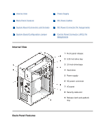
System Board Configuration Jumper Power Supply DC Power Cables DC Power Connector Pin Assignments Control Panel Connector (J9F2) Pin Assignments Internal View 1 Front-panel release 2 5.25-inch drive bay 3 3.5-inch drive bays 4 Hard drive 5 Power supply 6 AC power connector 7 I/O panel 8 Security - Dell Dimension 2100 | System Reference - Page 4
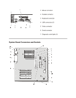
1 Mouse connector 2 Parallel connector 3 Keyboard connector 4 USB connectors (2) 5 Video connector 6 Serial connector 7 Diagnostic code lights (4) System Board Connectors and Sockets - Dell Dimension 2100 | System Reference - Page 5
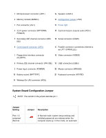
1 Microprocessor connector (J5H1) 12 Speaker (LS9A1) 2 Memory sockets (BANKn) 13 Configuration jumper (J7A1) 3 Fan connector (J3J1) 14 Power light 4 3.3-V power connector (OPTIONAL POWER) 15 Card connectors (natural color) (PCIn) 5 Secondary IDE channel connector (SEC IDE) 16 Serial - Dell Dimension 2100 | System Reference - Page 6
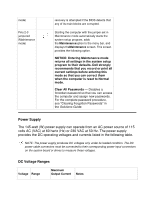
a forgotten password so that you can access the computer and assign new passwords. For the complete password procedure, see "Clearing Forgotten Passwords" in the Solutions Guide. Power Supply The 145-watt (W) power supply can operate from an AC power source of 115 volts AC (VAC) at 60 hertz - Dell Dimension 2100 | System Reference - Page 7
VDC -10.80 to - 13.20 VDC 0.300 A +5 VSB +4.75 to +5.25 VDC 1.2 A DC Power Cables The combined load on the +3.3-VDC and +5VDC outputs cannot exceed 85 W. The combined load on the +3.3- of up to 11.0 A to support disk start-up operations. The +5 volts standby (VSB) is sometimes called volts flea - Dell Dimension 2100 | System Reference - Page 8
DC Power Connector Pin Assignments The power-supply output voltages can be measured at the back (wire side) of the DC power connectors without disconnecting them. The following figures show the wire side of the connectors: DC Power Connector P1 - Dell Dimension 2100 | System Reference - Page 9
the ranges required for proper computer operation. 2 Pin 11 - PSON# is activated by pressing and releasing the power button while the power supply is in standby state. Activating PSON# connects the power supply's PSON# input to ground, thereby switching the power supply to full-on condition. DC - Dell Dimension 2100 | System Reference - Page 10
Common (black) 2 Common (black) 3 Common (black) 4 +3.3 VDC (orange) 5 +3.3 VDC (orange) 6 +3.3 VDC (orange) DC Power Connector P3 1 +12 VDC (yellow) 2 Common (black) 3 Common (black) 4 +5 VDC (red) DC Power Connectors P4, P5, and P6 1 +12 VDC (yellow) 2 Common (black) 3 Common (black) 4 +5 VDC (red - Dell Dimension 2100 | System Reference - Page 11
1 Hard-drive light (+) 2 Power light (+) 3 Hard-drive light (-) 4 Power light (-) 5 Reset switch 6 Power switch 7 Reset switch 8 Power switch 14 No pin 17 No pin 18 No pin Controls and Lights: Dell™ Dimension™ 2100 System Reference Front Panel Back Panel Front Panel - Dell Dimension 2100 | System Reference - Page 12
1 Floppy-drive access light - Lights up when a floppy drive is being accessed. 2 Power - Turns the computer on and off. Lights up when the computer is on. Press and hold for 4 seconds to shut down. 3 Hard-drive access light - Lights up when a hard drive is being accessed. Back Panel - Dell Dimension 2100 | System Reference - Page 13
drivers, the driver files are provided on the Dell Dimension ResourceCD. Device problems can often be corrected by reinstalling the appropriate drivers. Also, hardware manufacturers frequently provide updated drivers that support feature enhancements or that correct problems. Obtain updated drivers - Dell Dimension 2100 | System Reference - Page 14
drivers unless you first identify the specific driver intended for the hardware installed in your computer (see "Your Computer's Drivers"). Installing incorrect drivers might make your computer inoperable. 1. From the Windows desktop, insert the Dell Dimension ResourceCD into the CD or DVD drive - Dell Dimension 2100 | System Reference - Page 15
starts, follow the instructions on the screen. 3. When the InstallShield Wizard Complete window appears, remove the ResourceCD and clickFinish to restart the computer. 4. When you see the Windows desktop, reinsert the ResourceCD into the CD or DVD drive. 5. At the Welcome Dell System Owner screen - Dell Dimension 2100 | System Reference - Page 16
and a particular driver is not listed, then that driver is not required by your operating system. System Codes and Messages: Dell™ Dimension™ 2100 System Reference Diagnostic Codes POST Beep Codes System Messages Diagnostic Codes Your computer is equipped with four diagnostic code lights, which are - Dell Dimension 2100 | System Reference - Page 17
or off. If the power light is off, check the power supply. If the problem persists, see "Contacting Dell" in theSolutions Guide for instructions on obtaining technical assistance. System board is receiving power, but the BIOS is not executing. Remove all cards. If the computer still does not start - Dell Dimension 2100 | System Reference - Page 18
a BIOS test. If the problem persists, see "Contacting Dell" in the Solutions Guide for instructions on obtaining technical assistance. Memory failed to be sized or enabled. Reseat the memory modules. If the problem persists, remove all but one memory module, and then restart the computer. Repeat - Dell Dimension 2100 | System Reference - Page 19
has occurred. Remove all cards and restart the computer to determine if a resource conflict exists. If a conflict exists, resolve the conflict. If the problem persists, see "Contacting Dell" in the Solutions Guide for instructions on obtaining technical assistance. Video controller failed If the - Dell Dimension 2100 | System Reference - Page 20
and turned over control to the operating system. No action is necessary. POST Beep Codes If the monitor cannot display errors or problems, during power-on self-test (POST) the computer may emit a series of beeps, or beep code, that identifies the problem. If the computer emits a beep code and then - Dell Dimension 2100 | System Reference - Page 21
. 11 BIOS checksum error See "Contacting Dell" in the Solutions Guide for instructions on obtaining technical assistance. System Messages The first column in Table 3 lists (in alphabetical order) system messages that may appear on the screen during the boot routine or during normal computer - Dell Dimension 2100 | System Reference - Page 22
The hard drive is not working or is not configured correctly. Ensure that the drive is installed correctly in the chassis and defined correctly in the system setup program. Cache Memory Bad, Cache memory is not Do Not Enable Cache operating. See "Contacting Dell" in the Solutions Guide for - Dell Dimension 2100 | System Reference - Page 23
up. If the problem persists, you may need to replace the keyboard. No ROM Basic The operating system Enter the system setup program and cannot be located on drive confirm that drive A or drive C is A or drive C. properly identified. System Setup Program: Dell™ Dimension™ 2100 System Reference - Dell Dimension 2100 | System Reference - Page 24
, or remove any hardware in your computer • To set or change user-selectable options - for example, the user password Dell recommends that menu bar for accessing the main program screens. • The box on the left side of each screen lists options that define the installed hardware in the computer. - Dell Dimension 2100 | System Reference - Page 25
system password and setup password • Boot screen - Provides information about which device boots the computer • Exit screen - Provides your computer. 2. When the blue Dell logo appears, press . If you wait too long and the operating system begins to load into memory, let the computer complete - Dell Dimension 2100 | System Reference - Page 26
Main Screen Menu Options Option Function BIOS Version Displays the version of the BIOS being used. Processor Type Displays the type of microprocessor installed. Processor Speed Displays the internal speed of the microprocessor. Cache RAM Displays the cache random access memory. Service Tag - Dell Dimension 2100 | System Reference - Page 27
Advanced Screen Table 2. Advanced Screen Menu Options Option Function Boot Configuration Displays the Boot Configuration submenu. Peripheral Configuration Displays the Peripheral Configuration submenu. IDE Configuration Displays the IDE Configuration submenu. Diskette Configuration Displays - Dell Dimension 2100 | System Reference - Page 28
the computer is configured to support Plug and Play devices from the operating system or from the system BIOS. Leave this option set to No so that the BIOS handles all Plug and Play operations. Reset Config Data Numlock NOTE: Be sure that this option is set to No before running Dell Diagnostics - Dell Dimension 2100 | System Reference - Page 29
Table 4. Peripheral Configuration Submenu Options Option Function Serial port A Configures the serial port. Set this option to Auto (default), Enabled, or Disabled. Depending on the port setting, you can set the following additional options: Base I/OAddress If port is set to Enabled, available - Dell Dimension 2100 | System Reference - Page 30
allow support for legacy USB. Reserved (default) indicates that the IRQ is reserved for use by legacy devices. Availableindicates that a specific IRQ is available on the computer. IDE Configuration Submenu Table 5. IDE Configuration Submenu Options Option IDE Controller Function Configures - Dell Dimension 2100 | System Reference - Page 31
Submenu Table 6. Primary IDE Master Submenu Options Option Function Type Specifies the type of hard drive. Settings for this option are User, Auto, CD-ROM, ATAPI Removable, Other ATAPI, IDE Removable, and None. LBA Mode Determines LBA mode control. Set to Enabled (default) unless directed to - Dell Dimension 2100 | System Reference - Page 32
the method of moving data to and from the IDE drive. Options include PIO modes 0, 1, 2, 3, and 4. The PIO modes can improve the performance of a hard drive. (The higher the PIO number, the faster the transfer; most newer drives support PIO 4.) For the optimum transfer mode, set Type to Auto - Dell Dimension 2100 | System Reference - Page 33
When Write Protect this option is set toDisabled (default), the floppy disk is not protected unless the write-protect tab is in place. Enter> to view the event log. Clear All Event Clears all event logs when the computer restarts if set to Yes. Retains Logs the event log information if set to No - Dell Dimension 2100 | System Reference - Page 34
Video Configuration Submenu Table 9. Video Configuration Submenu Option Option Primary Video Adapter Function Selects Onboard or PCI as the active video controller when the computer boots. Security Screen - Dell Dimension 2100 | System Reference - Page 35
been assigned. Sets and confirms a supervisor password. Sets and confirms a user password. Clears the user password. Settings for this option are Yes or No (default). Boot Screen - Dell Dimension 2100 | System Reference - Page 36
Dell logo. Disabled displays the normal POST messages. Quick Boot When set to Enabled, this option shortens the POST by eliminating some tests. If set toDisabled (default), all POST tests occur. Restore on Determines what state the computer enters when AC power is restored AC/ Power after a power - Dell Dimension 2100 | System Reference - Page 37
Floppy • ARMD FDD • ARMD HDD • IDE-HDD • ATAPI CD-ROM • SCSI* • Network* • Disabled 2nd Boot Device 3rd Boot Device 4th Boot Device *Where SCSI or Network is the name of the installed device. Determines which device the computer tries to boot from if it cannot boot from the device selected for 1st - Dell Dimension 2100 | System Reference - Page 38
you have made, exits the system setup program, and restarts the computer. Load Setup Discards any changes you have made and reverts all Enter>. Then press the spacebar to select Yes or No at the confirmation pop-up menu, and press again. Save Custom Saves any changes you have made, but - Dell Dimension 2100 | System Reference - Page 39
to exit the program and restart the computer. Technical Specifications: Dell™ Dimension™ 2100 System Reference Microprocessor Power System Information Physical Expansion Bus Environmental Memory Regulatory Notices Drives IRQ Assignments Ports Default Dell-Installed Card Placement Video - Dell Dimension 2100 | System Reference - Page 40
processor's internal clock speed. 128-KB SRAM socket 370 System Information System chip set Data bus width Address bus width DMA channels Interrupt levels System BIOS chip Intel 810e or Intel 810 chip set 64 bits 32 bits two 15 4 Mb (512 KB) - Dell Dimension 2100 | System Reference - Page 41
connectors Card connector size Card connector data width (maximum) PCI (version 2.2) 33 MHz supports four three-quarter-length PCI cards 120 pins 32 bits Memory Architecture Memory sockets Memory capacities Minimum memory1 Maximum memory1 Frequency Clock cycle non-ECC SDRAM 168-pin modules two - Dell Dimension 2100 | System Reference - Page 42
3.3 V Data bus width 64 bits BIOS address F0000h 1 Video memory uses 1 or 2 MB of system memory (RAM). Total RAM reported is 1 or 2 MB less than RAM installed. 2 Up to 11 MB of system memory may be allocated to support DVMT Graphics. Drives Externally accessible Internally accessible Ports - Dell Dimension 2100 | System Reference - Page 43
connector two USB-compliant connectors 40-pin connector on PCI bus 40-pin connector on PCI bus 34-pin connector Video Video controller Intel 810e chip set with Dynamic Video Memory and 4-MB, 133-MHz display cache or Intel 810 chip set with Dynamic Video Memory Power DC power supply Wattage 145 - Dell Dimension 2100 | System Reference - Page 44
Height Width Depth Weight Environmental Temperature Operating Storage Relative humidity Maximum vibration Operating Storage Maximum shock Operating Storage Altitude Operating Storage 39 cm (15.375 inches) 16.8 cm (6.625 inches) 34 cm (13.375 inches) 9.9 kg (22 lb) 10� to 35�C (50� to 95�F)3 -40� to - Dell Dimension 2100 | System Reference - Page 45
IRQ9 IRQ2 Enables IRQ8 through IRQ15 IRQ10 IRQ3 Available4 IRQ11 IRQ4 Serial port IRQ12 IRQ5 Available IRQ13 IRQ6 Floppy/tape drive controller IRQ14 IRQ7 Parallel port IRQ15 System Resource RTC Available Available Available Mouse port Math coprocessor Primary IDE channel Secondary - Dell Dimension 2100 | System Reference - Page 46
Removing and Replacing Parts: Dell™ Dimension™ 2100 System Reference Overview Precautionary Measures Recommended Tools Cover Rotating the Power Supply Front panel 3.5-Inch Front Panel Insert Upper 3.5-Inch Drive Lower 3.5-Inch Floppy Drive Hard Drive Power Supply and Fan Assembly Control Panel - Dell Dimension 2100 | System Reference - Page 47
5.25-Inch Drive Overview Unless otherwise noted, each of the following procedures assumes: • You have the recommended tools. • You have performed the steps in "Precautionary Measures." • You have removed the computer cover. • You can replace or reinstall a part by performing the removal procedure in - Dell Dimension 2100 | System Reference - Page 48
lines from the computer. 4. Disconnect the power cable to your computer, and then press the power button to ground the system board. After you remove or replace parts in the computer, observe the following notice to prevent damage to the computer: NOTICE: Make sure that all other computer cables are - Dell Dimension 2100 | System Reference - Page 49
from the back of the computer, and press the power button before removing the computer cover. This computer continues to receive a small amount of power when the computer is turned off and attached to an electrical outlet (the systemboard power light is on when power is detected). 1. Face the front - Dell Dimension 2100 | System Reference - Page 50
, making sure to keep the bottom hooks aligned with the curves in the computer. 6. Gently squeeze the right and left sides of the computer together until the cover clicks into position. Rotating the Power Supply 1 Release latch 2 Power supply 3 Drive power cables 1. Remove the computer cover. - Dell Dimension 2100 | System Reference - Page 51
latch while lifting the power supply. 4. Rotate the power supply out of the computer while keeping the drive power cables clear. 5. When you rotate the power supply back into the computer, gently lift the and hold the drive cables out of the way. 6. Rotate the power supply into position until its - Dell Dimension 2100 | System Reference - Page 52
1 Front-panel release tab 2 Retaining hooks To remove the front panel: 1. Remove the computer cover. 2. While facing the front of the computer, press in the front-panel release tab the top of the computer. 3. Swing the front panel away from the computer, disengage the two retaining hooks at the - Dell Dimension 2100 | System Reference - Page 53
3.5-Inch Front Panel Insert 1 Insert 2 Tabs (2) 3 Release tab To remove a 3.5-inch insert: 1. Remove the front panel. 2. From the back of the front panel, press the release tab to the side. 3. Rotate the insert toward you, and remove it from the front panel. Upper 3.5-Inch Drive - Dell Dimension 2100 | System Reference - Page 54
bay plate To remove the upper 3.5-inch drive plate and install a new drive: 1. Remove the front panel. 2. Remove the 3.5-inch front panel insert. 3. Rotate the power supply away from the system board. While holding the power supply, place the computer in the upright position. 4. Remove the metal - Dell Dimension 2100 | System Reference - Page 55
-release rail tabs (2) To remove the 3.5-inch floppy drive from the lower bay: 1. Remove the front panel. 2. Rotate the power supply away from the system board. 3. While holding the power supply, place the computer in the upright position. 4. Disconnect the power and interface cables from the back - Dell Dimension 2100 | System Reference - Page 56
rail tabs (2) To remove the 5.25-inch drive: 1. Remove the front panel. 2. Rotate the power supply away from the system board. 3. While holding the power supply, place the computer in the upright position. 4. Disconnect the power and interface cables from the back of the drive. 5. Press the two - Dell Dimension 2100 | System Reference - Page 57
2 Clip 3 Hard drive To remove the primary hard drive: 1. Remove the front panel. 2. Rotate the power supply away from the system board. 3. While holding the power supply, place the computer in the upright position. 4. Remove the two screws securing the hard drive to the front of the computer frame - Dell Dimension 2100 | System Reference - Page 58
you removed. 4. Connect a power supply cable and the hard drive interface cable to the new drive. Power Supply and Fan Assembly 1 Power-supply retaining clips 2 Power supply and fan assembly To remove the power supply and fan assembly: 1. Disconnect the AC power cable from the computer. 2. Remove - Dell Dimension 2100 | System Reference - Page 59
power supply and fan assembly out of the computer. Control Panel 1 Control panel assembly 2 Mounting tabs To remove the control panel: 1. Remove the front cover. 2. Disconnect the control panel from the system board. 3. Press the mounting tabs to release the control panel and remove the control - Dell Dimension 2100 | System Reference - Page 60
2 Card 3 System-board card connector 4 Card mounting bracket and screw To install a card: 1. Remove the computer cover. 2. Rotate the power supply. 3. Choose a system-board card connector for the card. 4. Unscrew and remove the metal filler bracket that covers the card-slot opening for the card slot - Dell Dimension 2100 | System Reference - Page 61
also keep dust and dirt out of your computer. Memory 1 Cutouts (2) 2 Connector 3 Memory module 4 Notches (2) 5 Securing clips (2) To install a memory module: 1. Remove the computer cover. 2. Rotate the power supply. 3. If necessary, remove a memory module: a. Press out the securing clip at each - Dell Dimension 2100 | System Reference - Page 62
module with the crossbars in the connector. NOTICE: To avoid breaking the memory module, do not press near the middle of the module. 6. Insert the module straight down into the connector, making sure that it fits into the vertical guides at each end of the connector. Press firmly on the ends of - Dell Dimension 2100 | System Reference - Page 63
in the preceding figure. To remove and replace the microprocessor and heat sink: 1. Remove the computer cover. 2. Rotate the power supply. 3. Locate the microprocessor socket on the system board. 4. Release the metal clip that secures the heat sink and fan assembly to the microprocessor socket - Dell Dimension 2100 | System Reference - Page 64
Replace the computer cover, and then reconnect your computer and peripherals to their electrical outlets and turn them on. As the computer boots, that secures the chip in (or releases it from) the socket. 1. To remove the chip, pull the microprocessor-socket release lever out to unlock it and then - Dell Dimension 2100 | System Reference - Page 65
the beveled corner. The pin-1 corner of the socket, labeled "1," is the front-left corner of the socket as you face the back of the computer. 1 Pin-1 corners of chip and socket aligned 5. Install the microprocessor chip in the socket (as shown in the preceding figure). NOTICE: You must position the - Dell Dimension 2100 | System Reference - Page 66
c. Set the chip lightly in the socket and make sure that all pins are headed it is incorrectly installed. Replace the battery only with the same or equivalent type recommended by the manufacturer. Discard used batteries according to the manufacturer's instructions. To remove the 3-volt (V), CR2032 - Dell Dimension 2100 | System Reference - Page 67
new battery with the "+" side facing up. 2. Rotate the power supply back into place, replace the computer cover, and reconnect your computer and devices to their electrical outlets and turn them on. 3. Reboot the computer, press when the blue Dell logo screen appears to enter the system setup - Dell Dimension 2100 | System Reference - Page 68
board is replaced. 2. Remove the computer cover. 3. Remove the power supply. 4. Disconnect any cables connected to cards, and remove these cards. 5. Disconnect all internal cables from the system board. 6. Remove the heat sink assembly. 7. Remove the microprocessor. 8. Remove the memory modules. - Dell Dimension 2100 | System Reference - Page 69
heat sink, the memory modules, and the cards that you removed from the old system board. To configure the system after you install a replacement board: 1. Install the jumper plug on pins 2 and 3 of configuration jumper J7A1 to select Maintenance mode operation. 2. Replace the computer cover, and - Dell Dimension 2100 | System Reference - Page 70
5. Turn off the computer, remove the computer cover, and replace the jumper plug on pins 1 and 2 ofconfiguration jumper J7A1 to select Normal mode operation. 6. Replace the cover, and start the computer. 7. Re-enter the system setup program, and reset the system configuration information.
-
 1
1 -
 2
2 -
 3
3 -
 4
4 -
 5
5 -
 6
6 -
 7
7 -
8
-
9
-
10
-
11
-
12
-
13
-
14
-
15
-
16
-
17
-
18
-
19
-
20
-
21
-
22
-
23
-
24
-
25
-
26
-
27
-
28
-
29
-
30
-
31
-
32
-
33
-
34
-
35
-
36
-
37
-
38
-
39
-
40
-
41
-
42
-
43
-
44
-
45
-
46
-
47
-
48
-
49
-
50
-
51
-
52
-
53
-
54
-
55
-
56
-
57
-
58
-
59
-
60
-
61
-
62
-
63
-
64
-
65
-
66
-
67
-
68
-
69
-
70
 |
 |
Conventions: Dell™ Dimension™ 2100 System
Reference
Notes, Notices, and Cautions
Typographical Conventions
The following subsections describe notational conventions used in this
document.
Notes, Notices, and Cautions
Throughout this guide, blocks of text may be accompanied by an icon and
printed in bold type or in italic type. These blocks are notes, notices, and
cautions, and they are used as follows:
NOTE: A NOTE indicates important information that helps you make better use of
your computer.
NOTICE: A NOTICE indicates either potential damage to hardware or
loss of data and tells you how to avoid the problem.
CAUTION: A CAUTION indicates a potential for property damage, personal
injury, or death.
Typographical Conventions
The following list defines (where appropriate) and illustrates typographical
conventions used as visual cues for specific elements of text throughout this
document:
•
Interface components
are window titles, button and icon names, menu
names and selections, and other options that appear on the monitor
screen or display. They are presented in bold.
Example: Click
OK
.