Dell Dimension 2100 System Reference - Page 65
socket to avoid permanent damage to the chip and the computer when
 |
View all Dell Dimension 2100 manuals
Add to My Manuals
Save this manual to your list of manuals |
Page 65 highlights
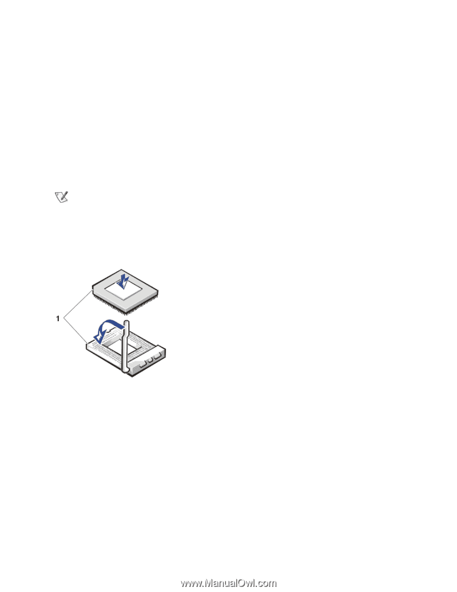
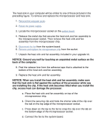
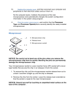
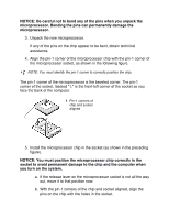
NOTICE: Be careful not to bend any of the pins when you unpack the microprocessor. Bending the pins can permanently damage the microprocessor. 3. Unpack the new microprocessor. If any of the pins on the chip appear to be bent, obtain technical assistance. 4. Align the pin-1 corner of the microprocessor chip with the pin-1 corner of the microprocessor socket, as shown in the following figure. NOTE: You must identify the pin-1 corner to correctly position the chip. The pin-1 corner of the microprocessor is the beveled corner. The pin-1 corner of the socket, labeled "1," is the front-left corner of the socket as you face the back of the computer. 1 Pin-1 corners of chip and socket aligned 5. Install the microprocessor chip in the socket (as shown in the preceding figure). NOTICE: You must position the microprocessor chip correctly in the socket to avoid permanent damage to the chip and the computer when you turn on the system. a. If the release lever on the microprocessor socket is not all the way out, move it to that position now. b. With the pin-1 corners of the chip and socket aligned, align the pins on the chip with the holes in the socket.
-
 1
1 -
2
-
3
-
4
-
5
-
6
-
7
-
8
-
9
-
10
-
11
-
12
-
13
-
14
-
15
-
16
-
17
-
18
-
19
-
20
-
21
-
22
-
23
-
24
-
25
-
26
-
27
-
28
-
29
-
30
-
31
-
32
-
33
-
34
-
35
-
36
-
37
-
38
-
39
-
40
-
41
-
42
-
43
-
44
-
45
-
46
-
47
-
48
-
49
-
50
-
51
-
52
-
53
-
54
-
55
-
56
-
57
-
58
-
59
-
 60
60 -
 61
61 -
 62
62 -
 63
63 -
 64
64 -
 65
65 -
 66
66 -
 67
67 -
 68
68 -
 69
69 -
 70
70
 |
 |