Dell External OEMR R620 Owners Manual - Page 17
NIC Indicator Codes, Four integrated 10/100/1000 Mbps NIC connectors
 |
View all Dell External OEMR R620 manuals
Add to My Manuals
Save this manual to your list of manuals |
Page 17 highlights
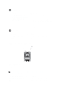
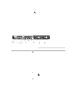
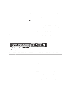
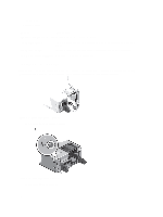
Item Indicator, Button, or Icon Connector 2 System identification connector 3 iDRAC7 Enterprise port 4 PCIe expansion card slot (riser 1) 5 Serial connector 6 Video connector 7 PCIe expansion card slot (riser 2) 8 USB connectors (2) 9 Ethernet connectors (4) 10 PCIe expansion card slot (riser 3) 11 Power supply (PSU1) 12 Power supply (PSU2) NIC Indicator Codes Description To reset iDRAC (if not disabled in F2 iDRAC setup) press and hold for more than 15 seconds. Allows you to connect the optional system status indicator assembly through the optional cable management arm. Dedicated management port. NOTE: The port is available for use only if the iDRAC7 Enterprise license is installed on your system. Allows you to connect a PCIe expansion card. Allows you to connect a serial device to the system. Allows you to connect a VGA display to the system. Allows you to connect a PCIe expansion card. Allows you to connect USB devices to the system. The ports are USB 2.0-compliant. Four integrated 10/100/1000 Mbps NIC connectors or Four integrated connectors: • Two integrated 10/100/1000 Mbps NIC connectors • Two integrated 100 Mbps/1 Gbps/10 Gbps SFP+ connectors Allows you to connect a PCIe expansion card. AC 495 W, 750 W, or 1100 W Or DC 1100 W (when available) Figure 7. NIC Indicator 17
-
 1
1 -
2
-
3
-
4
-
5
-
6
-
7
-
8
-
9
-
10
-
11
-
 12
12 -
 13
13 -
 14
14 -
 15
15 -
 16
16 -
 17
17 -
 18
18 -
 19
19 -
 20
20 -
 21
21 -
 22
22 -
23
-
24
-
25
-
26
-
27
-
28
-
29
-
30
-
31
-
32
-
33
-
34
-
35
-
36
-
37
-
38
-
39
-
40
-
41
-
42
-
43
-
44
-
45
-
46
-
47
-
48
-
49
-
50
-
51
-
52
-
53
-
54
-
55
-
56
-
57
-
58
-
59
-
60
-
61
-
62
-
63
-
64
-
65
-
66
-
67
-
68
-
69
-
70
-
71
-
72
-
73
-
74
-
75
-
76
-
77
-
78
-
79
-
80
-
81
-
82
-
83
-
84
-
85
-
86
-
87
-
88
-
89
-
90
-
91
-
92
-
93
-
94
-
95
-
96
-
97
-
98
-
99
-
100
-
101
-
102
-
103
-
104
-
105
-
106
-
107
-
108
-
109
-
110
-
111
-
112
-
113
-
114
-
115
-
116
-
117
-
118
-
119
-
120
-
121
-
122
-
123
-
124
-
125
-
126
-
127
-
128
-
129
-
130
-
131
-
132
-
133
 |
 |
