Dell External OEMR R620 Owners Manual - Page 95
Removing and Installing the System Board
 |
View all Dell External OEMR R620 manuals
Add to My Manuals
Save this manual to your list of manuals |
Page 95 highlights
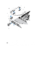
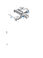
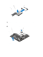
a. mini SAS cable connector b. metal tab c. connector on the system board 6. Disconnect all other cables from the system board. CAUTION: Take care not to damage the system identification button while removing the system board from the chassis. 7. Grasp the system-board holder, lift the blue release pin, slide the system board toward the front of the system, and lift the system board out of the chassis. CAUTION: Do not lift the system board assembly by grasping a memory module, processor, or other components. Figure 52. Removing and Installing the System Board 1. system board 2. system-board holder 3. release pin 95
-
 1
1 -
2
-
3
-
4
-
5
-
6
-
7
-
8
-
9
-
10
-
11
-
12
-
13
-
14
-
15
-
16
-
17
-
18
-
19
-
20
-
21
-
22
-
23
-
24
-
25
-
26
-
27
-
28
-
29
-
30
-
31
-
32
-
33
-
34
-
35
-
36
-
37
-
38
-
39
-
40
-
41
-
42
-
43
-
44
-
45
-
46
-
47
-
48
-
49
-
50
-
51
-
52
-
53
-
54
-
55
-
56
-
57
-
58
-
59
-
60
-
61
-
62
-
63
-
64
-
65
-
66
-
67
-
68
-
69
-
70
-
71
-
72
-
73
-
74
-
75
-
76
-
77
-
78
-
79
-
80
-
81
-
82
-
83
-
84
-
85
-
86
-
87
-
88
-
89
-
 90
90 -
 91
91 -
 92
92 -
 93
93 -
 94
94 -
 95
95 -
 96
96 -
 97
97 -
 98
98 -
 99
99 -
 100
100 -
101
-
102
-
103
-
104
-
105
-
106
-
107
-
108
-
109
-
110
-
111
-
112
-
113
-
114
-
115
-
116
-
117
-
118
-
119
-
120
-
121
-
122
-
123
-
124
-
125
-
126
-
127
-
128
-
129
-
130
-
131
-
132
-
133
 |
 |

a. mini SAS cable connector
b. metal tab
c. connector on the system board
6.
Disconnect all other cables from the system board.
CAUTION: Take care not to damage the system identification button while removing the system board from the
chassis.
7.
Grasp the system-board holder, lift the blue release pin, slide the system board toward the front of the system, and
lift the system board out of the chassis.
CAUTION: Do not lift the system board assembly by grasping a memory module, processor, or other components.
Figure 52. Removing and Installing the System Board
1. system board
2. system-board holder
3. release pin
95