Dell External OEMR R620 Owners Manual - Page 39
Cooling Shroud, Removing The Cooling Shroud
 |
View all Dell External OEMR R620 manuals
Add to My Manuals
Save this manual to your list of manuals |
Page 39 highlights
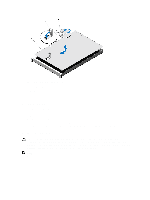
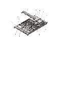
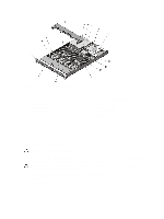
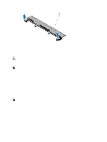
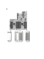
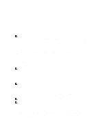
Figure 13. Inside the System-10 Hard Drive System 1. control panel 2. cable securing clip 3. cooling fans (7) 4. cable securing bracket 5. cooling shroud 6. power supplies (2) 7. chassis intrusion switch 8. riser card 3 9. network daughter card Cooling Shroud 10. riser card 1 11. storage controller card 12. network daughter card cooling shroud 13. DIMMs (24) 14. heat sink for processor 2 15. hard-drive backplane 16. hard drives (10) Removing The Cooling Shroud CAUTION: Many repairs may only be done by a certified service technician. You should only perform troubleshooting and simple repairs as authorized in your product documentation, or as directed by the online or telephone service and support team. Damage due to servicing that is not authorized by Dell is not covered by your warranty. Read and follow the safety instructions that came with the product. CAUTION: Never operate your system with the cooling shroud removed. The system may get overheated quickly, resulting in shutdown of the system and loss of data. 1. Turn off the system, including any attached peripherals, and disconnect the system from the electrical outlet and peripherals. 2. Open the system. 3. Hold the touch points and lift the shroud away from the system. 39
-
 1
1 -
2
-
3
-
4
-
5
-
6
-
7
-
8
-
9
-
10
-
11
-
12
-
13
-
14
-
15
-
16
-
17
-
18
-
19
-
20
-
21
-
22
-
23
-
24
-
25
-
26
-
27
-
28
-
29
-
30
-
31
-
32
-
33
-
 34
34 -
 35
35 -
 36
36 -
 37
37 -
 38
38 -
 39
39 -
 40
40 -
 41
41 -
 42
42 -
 43
43 -
 44
44 -
45
-
46
-
47
-
48
-
49
-
50
-
51
-
52
-
53
-
54
-
55
-
56
-
57
-
58
-
59
-
60
-
61
-
62
-
63
-
64
-
65
-
66
-
67
-
68
-
69
-
70
-
71
-
72
-
73
-
74
-
75
-
76
-
77
-
78
-
79
-
80
-
81
-
82
-
83
-
84
-
85
-
86
-
87
-
88
-
89
-
90
-
91
-
92
-
93
-
94
-
95
-
96
-
97
-
98
-
99
-
100
-
101
-
102
-
103
-
104
-
105
-
106
-
107
-
108
-
109
-
110
-
111
-
112
-
113
-
114
-
115
-
116
-
117
-
118
-
119
-
120
-
121
-
122
-
123
-
124
-
125
-
126
-
127
-
128
-
129
-
130
-
131
-
132
-
133
 |
 |
