Dell Force10 E600i Quick Start Guide - Page 19
E1200i AC Power Modules, install the AC-cord retainer over all power cords. The E1200i AC chassis
 |
View all Dell Force10 E600i manuals
Add to My Manuals
Save this manual to your list of manuals |
Page 19 highlights
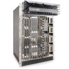
Step Task 3 Loosen the retaining screw and remove PEM safety cover. 4 Slide the backplane connector end of the PEM into Power Supply Slot 1 or 3. Secure the PEM to the chassis by tighten the two locking screws. E1200i AC Power Modules When installing the AC power supplies in the E1200i system, make note of the following: • E1200i ExaScale AC system: The E1200i AC system requires a minimum of 3 AC power supplies in a shelf (0, 1, 2 or 3, 4, 5) to operate. For full redundancy use 6 power supplies so that if one power supply fails in one shelf, the system remains operational operates with the 3 power supplies in the other shelf. To comply with safety agency and EMI regulations, you must install the AC-cord retainer over all power cords. The E1200i AC chassis contains 6 AC power supply slots. • E1200iTeraScale AC system: The E1200i AC system requires a minimum of two AC power supplies to operate, three for power redundancy, four for facility redundancy (2+2), and 6 for 3+3 redundancy. To comply with safety agency and EMI regulations, you must install the AC-cord retainer over all power cords. The E1200i AC chassis contains six AC power supply slots. NOTE: If you are installing only two power supplies, they must be installed in the same row. FTOS will generate an error message if the two power supplies are not in the same row. NOTE: The On/Standby switch disconnects power to the rest of the chassis from all 6 AC power supplies. When the AC cord is attached, power supply fans will spin and the LEDs will indicate status while the On/Standby switch is in Standby. CAUTION: An E1200i AC power supply still has power after extraction, and has completely powered off when the fans have stopped rotating. When replacing a power supply, to avoid arcing and discoloration of the supply and the chassis pins, please wait for the fans to stop rotating before reinserting the supply. Step Task 1 Make sure that the On/Standby switch, located on the left side of plug AC-0, is in the Standby (up) position. Installing the Hardware 17
-
 1
1 -
2
-
3
-
4
-
5
-
6
-
7
-
8
-
9
-
10
-
11
-
12
-
13
-
 14
14 -
 15
15 -
 16
16 -
 17
17 -
 18
18 -
 19
19 -
 20
20 -
 21
21 -
 22
22 -
 23
23 -
 24
24 -
25
-
26
-
27
-
28
-
29
-
30
-
31
-
32
-
33
-
34
-
35
-
36
-
37
-
38
-
39
-
40
-
41
-
42
-
43
-
44
-
45
-
46
-
47
-
48
-
49
-
50
 |
 |
