Dell Inspiron 13 7368 2-in-1 Inspiron 13 7000 series 2-in-1 Service Manual
Dell Inspiron 13 7368 2-in-1 Manual
 |
View all Dell Inspiron 13 7368 2-in-1 manuals
Add to My Manuals
Save this manual to your list of manuals |
Dell Inspiron 13 7368 2-in-1 manual content summary:
- Dell Inspiron 13 7368 2-in-1 | Inspiron 13 7000 series 2-in-1 Service Manual - Page 1
Inspiron 13 7000 series 2-in-1 Service Manual Computer Model: Inspiron 13-7368 Regulatory Model: P69G Regulatory Type: P69G001 - Dell Inspiron 13 7368 2-in-1 | Inspiron 13 7000 series 2-in-1 Service Manual - Page 2
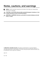
use of your computer. CAUTION: A CAUTION indicates either potential damage to hardware or loss of data and tells you how to avoid the problem. WARNING: A WARNING indicates a potential for property damage, personal injury, or death. © 2016 Dell Inc. All rights reserved. This product is protected by - Dell Inspiron 13 7368 2-in-1 | Inspiron 13 7000 series 2-in-1 Service Manual - Page 3
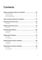
Contents Before working inside your computer 12 Before you begin 12 Safety instructions 12 Recommended tools 13 After working inside your computer 15 Removing the base cover 16 Procedure...16 Replacing the base cover 19 Procedure...19 Removing - Dell Inspiron 13 7368 2-in-1 | Inspiron 13 7000 series 2-in-1 Service Manual - Page 4
Removing the solid-state drive 29 Prerequisites...29 Procedure...29 Replacing the solid-state drive 31 Procedure...31 Post-requisites 32 Removing the coin-cell battery 33 Prerequisites...33 Procedure...33 Replacing the coin-cell battery 35 Procedure...35 Post-requisites 35 Removing the - Dell Inspiron 13 7368 2-in-1 | Inspiron 13 7000 series 2-in-1 Service Manual - Page 5
Removing the speakers 43 Prerequisites...43 Procedure...43 Replacing the speakers 45 Procedure...45 Post-requisites 45 Removing the fan 46 Prerequisites...46 Procedure...46 Replacing the fan 48 Procedure...48 Post-requisites 48 Removing the heat sink 49 Prerequisites...49 Procedure...49 - Dell Inspiron 13 7368 2-in-1 | Inspiron 13 7000 series 2-in-1 Service Manual - Page 6
Removing the power and volume-buttons board 55 Prerequisites...55 Procedure...55 Replacing the power and volume-buttons board 57 Procedure...57 Post-requisites 57 Removing the status-light board 58 Prerequisites...58 Procedure...58 Replacing the status-light board 61 Procedure...61 Post- - Dell Inspiron 13 7368 2-in-1 | Inspiron 13 7000 series 2-in-1 Service Manual - Page 7
74 Removing the system board 75 Prerequisites...75 Procedure...75 Replacing the system board 80 Procedure...80 Post-requisites 81 Entering the Service Tag in the BIOS setup program 81 Removing the keyboard 82 Prerequisites...82 Procedure...83 Replacing the keyboard 86 Procedure...86 Post - Dell Inspiron 13 7368 2-in-1 | Inspiron 13 7000 series 2-in-1 Service Manual - Page 8
Removing the display panel 90 Prerequisites...90 Procedure...90 Replacing the display panel 93 Procedure...93 Post-requisites 93 Removing the display back-cover and antenna assembly 94 Prerequisites...94 Procedure...94 Replacing the display back-cover and antenna assembly 96 Procedure...96 Post - Dell Inspiron 13 7368 2-in-1 | Inspiron 13 7000 series 2-in-1 Service Manual - Page 9
Removing the sensor board 103 Prerequisites 103 Procedure...103 Replacing the sensor board 105 Procedure...105 Post-requisites 105 Flashing the BIOS 106 Technology and components 107 Audio...107 Downloading the audio driver 107 Identifying the audio controller 107 Changing the audio settings - Dell Inspiron 13 7368 2-in-1 | Inspiron 13 7000 series 2-in-1 Service Manual - Page 10
Setting up the wireless display 116 USB...117 Downloading the USB 3.0 driver 117 Enabling or disabling the USB in BIOS setup program 117 Fixing a no-boot issue caused by USB emulation 118 Wi-Fi...118 Turning on or off Wi-Fi 118 Configuring Wi-Fi 118 Bluetooth...119 Turning on or off Bluetooth - Dell Inspiron 13 7368 2-in-1 | Inspiron 13 7000 series 2-in-1 Service Manual - Page 11
Identifying the processors in Windows 129 Checking the processor usage in the task manager 130 Operating System 130 Service Tag location 130 Device drivers 131 Intel Dynamic Platform and Thermal Framework 131 Intel Chipset Software Installation Utility 131 Intel HD Graphics 520 driver 132 - Dell Inspiron 13 7368 2-in-1 | Inspiron 13 7000 series 2-in-1 Service Manual - Page 12
you ordered. Before you begin 1 Save and close all open files and exit all open applications. 2 Shut down your computer. The shut-down instruction varies depending on the operating system installed on your computer. - Windows 10: Click or tap Start → Power → Shut down. - Windows 8.1: On the Start - Dell Inspiron 13 7368 2-in-1 | Inspiron 13 7000 series 2-in-1 Service Manual - Page 13
pins and contacts. CAUTION: You should only perform troubleshooting and repairs as authorized or directed by the Dell technical assistance team. Damage due to servicing that is not authorized by Dell is not covered by your warranty. See the safety instructions that shipped with the product or at www - Dell Inspiron 13 7368 2-in-1 | Inspiron 13 7000 series 2-in-1 Service Manual - Page 14
• Plastic scribe 14 - Dell Inspiron 13 7368 2-in-1 | Inspiron 13 7000 series 2-in-1 Service Manual - Page 15
After working inside your computer CAUTION: Leaving stray or loose screws inside your computer may severely damage your computer. 1 Replace all screws and ensure that no stray screws remain inside your computer. 2 Connect any external devices, peripherals, or cables you removed before working on - Dell Inspiron 13 7368 2-in-1 | Inspiron 13 7000 series 2-in-1 Service Manual - Page 16
shipped with your computer and follow the steps in Before working inside your computer. After working inside your computer, follow the instructions in After working inside your computer. For more safety best practices, see the Regulatory Compliance home page at www.dell.com/regulatory_compliance - Dell Inspiron 13 7368 2-in-1 | Inspiron 13 7000 series 2-in-1 Service Manual - Page 17
2 Remove the screws that secure the base cover to the palm-rest assembly. 1 screws (9) 3 palm-rest assembly 2 base cover 17 - Dell Inspiron 13 7368 2-in-1 | Inspiron 13 7000 series 2-in-1 Service Manual - Page 18
3 Using a plastic scribe, release the tabs that secure the base cover to the palm-rest assembly and remove the base cover off the palm-rest assembly. 1 plastic scribe 3 base cover 2 palm-rest assembly 18 - Dell Inspiron 13 7368 2-in-1 | Inspiron 13 7000 series 2-in-1 Service Manual - Page 19
shipped with your computer and follow the steps in Before working inside your computer. After working inside your computer, follow the instructions in After working inside your computer. For more safety best practices, see the Regulatory Compliance home page at www.dell.com/regulatory_compliance - Dell Inspiron 13 7368 2-in-1 | Inspiron 13 7000 series 2-in-1 Service Manual - Page 20
shipped with your computer and follow the steps in Before working inside your computer. After working inside your computer, follow the instructions in After working inside your computer. For more safety best practices, see the Regulatory Compliance home page at www.dell.com/regulatory_compliance - Dell Inspiron 13 7368 2-in-1 | Inspiron 13 7000 series 2-in-1 Service Manual - Page 21
3 Lift the battery off the palm-rest assembly. 1 system board 3 screws (4) 5 battery 2 battery cable 4 palm-rest assembly 4 Press and hold the power button for five seconds to ground the system board. 21 - Dell Inspiron 13 7368 2-in-1 | Inspiron 13 7000 series 2-in-1 Service Manual - Page 22
shipped with your computer and follow the steps in Before working inside your computer. After working inside your computer, follow the instructions in After working inside your computer. For more safety best practices, see the Regulatory Compliance home page at www.dell.com/regulatory_compliance - Dell Inspiron 13 7368 2-in-1 | Inspiron 13 7000 series 2-in-1 Service Manual - Page 23
shipped with your computer and follow the steps in Before working inside your computer. After working inside your computer, follow the instructions in After working inside your computer. For more safety best practices, see the Regulatory Compliance home page at www.dell.com/regulatory_compliance - Dell Inspiron 13 7368 2-in-1 | Inspiron 13 7000 series 2-in-1 Service Manual - Page 24
Procedure 1 Lift the Mylar to access the memory module. 1 memory module 2 Mylar 2 Use your fingertips to carefully spread apart the securing-clips on each end of the memory-module slot until the memory module pops up. 24 - Dell Inspiron 13 7368 2-in-1 | Inspiron 13 7000 series 2-in-1 Service Manual - Page 25
3 Remove the memory module from the memory-module slot. 1 securing clips (2) 3 memory-module slot 2 memory module 25 - Dell Inspiron 13 7368 2-in-1 | Inspiron 13 7000 series 2-in-1 Service Manual - Page 26
shipped with your computer and follow the steps in Before working inside your computer. After working inside your computer, follow the instructions in After working inside your computer. For more safety best practices, see the Regulatory Compliance home page at www.dell.com/regulatory_compliance - Dell Inspiron 13 7368 2-in-1 | Inspiron 13 7000 series 2-in-1 Service Manual - Page 27
3 Slide the memory module firmly into the slot at an angle and press the memory module down until it clicks into place. NOTE: If you do not hear the click, remove the memory module and reinstall it. 1 memory module 3 notch 5 Mylar Post-requisites 1 Replace the battery. 2 memory-module slot 4 tab - Dell Inspiron 13 7368 2-in-1 | Inspiron 13 7000 series 2-in-1 Service Manual - Page 28
2 Replace the base cover. 28 - Dell Inspiron 13 7368 2-in-1 | Inspiron 13 7000 series 2-in-1 Service Manual - Page 29
shipped with your computer and follow the steps in Before working inside your computer. After working inside your computer, follow the instructions in After working inside your computer. For more safety best practices, see the Regulatory Compliance home page at www.dell.com/regulatory_compliance - Dell Inspiron 13 7368 2-in-1 | Inspiron 13 7000 series 2-in-1 Service Manual - Page 30
2 Slide and remove the solid-state drive off the system board. 1 screw 3 solid-state drive slot 5 palm-rest assembly 2 solid-state drive 4 system board 30 - Dell Inspiron 13 7368 2-in-1 | Inspiron 13 7000 series 2-in-1 Service Manual - Page 31
shipped with your computer and follow the steps in Before working inside your computer. After working inside your computer, follow the instructions in After working inside your computer. For more safety best practices, see the Regulatory Compliance home page at www.dell.com/regulatory_compliance - Dell Inspiron 13 7368 2-in-1 | Inspiron 13 7000 series 2-in-1 Service Manual - Page 32
2 Press the other end of the solid-state drive and replace the screw that secures the solid-state drive to the palm-rest assembly. 1 screw 3 solid-state drive slot 5 palm-rest assembly Post-requisites 1 Replace the battery. 2 Replace the base cover. 2 solid-state drive 4 system board 32 - Dell Inspiron 13 7368 2-in-1 | Inspiron 13 7000 series 2-in-1 Service Manual - Page 33
shipped with your computer and follow the steps in Before working inside your computer. After working inside your computer, follow the instructions in After working inside your computer. For more safety best practices, see the Regulatory Compliance home page at www.dell.com/regulatory_compliance - Dell Inspiron 13 7368 2-in-1 | Inspiron 13 7000 series 2-in-1 Service Manual - Page 34
2 Peel the coin-cell battery off the palm-rest assembly. 1 I/O board 3 coin-cell battery 2 coin-cell battery cable 4 palm-rest assembly 34 - Dell Inspiron 13 7368 2-in-1 | Inspiron 13 7000 series 2-in-1 Service Manual - Page 35
shipped with your computer and follow the steps in Before working inside your computer. After working inside your computer, follow the instructions in After working inside your computer. For more safety best practices, see the Regulatory Compliance home page at www.dell.com/regulatory_compliance - Dell Inspiron 13 7368 2-in-1 | Inspiron 13 7000 series 2-in-1 Service Manual - Page 36
shipped with your computer and follow the steps in Before working inside your computer. After working inside your computer, follow the instructions in After working inside your computer. For more safety best practices, see the Regulatory Compliance home page at www.dell.com/regulatory_compliance - Dell Inspiron 13 7368 2-in-1 | Inspiron 13 7000 series 2-in-1 Service Manual - Page 37
3 Slide and remove the wireless card from the wireless-card slot. 1 screw 3 wireless-card slot 5 antenna cables (2) 2 wireless-card bracket 4 wireless card 37 - Dell Inspiron 13 7368 2-in-1 | Inspiron 13 7000 series 2-in-1 Service Manual - Page 38
your computer. After working inside your computer, follow the instructions in After working inside your computer. For more safety best following table provides the antenna-cable color scheme for the wireless card supported by your computer. Connectors on the wireless card Main (white triangle) - Dell Inspiron 13 7368 2-in-1 | Inspiron 13 7000 series 2-in-1 Service Manual - Page 39
5 Replace the screw that secures the wireless card bracket to the wireless card. 1 tab 3 wireless-card slot 5 antenna cables (2) 7 screw Post-requisites 1 Replace the battery. 2 Replace the base cover. 2 notch 4 wireless card 6 wireless card bracket 39 - Dell Inspiron 13 7368 2-in-1 | Inspiron 13 7000 series 2-in-1 Service Manual - Page 40
shipped with your computer and follow the steps in Before working inside your computer. After working inside your computer, follow the instructions in After working inside your computer. For more safety best practices, see the Regulatory Compliance home page at www.dell.com/regulatory_compliance - Dell Inspiron 13 7368 2-in-1 | Inspiron 13 7000 series 2-in-1 Service Manual - Page 41
2 Using a plastic scribe, pry the keyboard daughter-board off the palm-rest assembly. 1 keyboard cable 3 palm-rest assembly 5 keyboard daughter-board cable 7 status-light board-cable 9 keyboard daughter-board 2 keyboard-backlight cable 4 touch-pad cable 6 latch 8 plastic scribe 41 - Dell Inspiron 13 7368 2-in-1 | Inspiron 13 7000 series 2-in-1 Service Manual - Page 42
shipped with your computer and follow the steps in Before working inside your computer. After working inside your computer, follow the instructions in After working inside your computer. For more safety best practices, see the Regulatory Compliance home page at www.dell.com/regulatory_compliance - Dell Inspiron 13 7368 2-in-1 | Inspiron 13 7000 series 2-in-1 Service Manual - Page 43
working inside your computer. After working inside your computer, follow the instructions in After working inside your computer. For more safety best practices . 3 Remove the speaker cable from the routing guides on the palm-rest assembly. 4 Note the position of the rubber grommets before lifting - Dell Inspiron 13 7368 2-in-1 | Inspiron 13 7000 series 2-in-1 Service Manual - Page 44
5 Remove the speakers from the alignment posts and lift the speakers off the palm-rest assembly. 1 system board 3 palm-rest assembly 5 tape (2) 7 speakers (2) 2 speaker cable 4 routing guides 6 alignment posts 8 rubber grommets (5) 44 - Dell Inspiron 13 7368 2-in-1 | Inspiron 13 7000 series 2-in-1 Service Manual - Page 45
your computer. After working inside your computer, follow the instructions in After working inside your computer. For more safety best pushed up while replacing the speaker. 3 Route the speaker cable through the routing guides on the palm-rest assembly. 4 Adhere the pieces of tape that secure the - Dell Inspiron 13 7368 2-in-1 | Inspiron 13 7000 series 2-in-1 Service Manual - Page 46
shipped with your computer and follow the steps in Before working inside your computer. After working inside your computer, follow the instructions in After working inside your computer. For more safety best practices, see the Regulatory Compliance home page at www.dell.com/regulatory_compliance - Dell Inspiron 13 7368 2-in-1 | Inspiron 13 7000 series 2-in-1 Service Manual - Page 47
3 Move the antenna cables out of the way and lift the fan off the palm-rest assembly. 1 antenna cables (2) 3 fan 5 fan cable 2 palm-rest assembly 4 screws (2) 6 system board 47 - Dell Inspiron 13 7368 2-in-1 | Inspiron 13 7000 series 2-in-1 Service Manual - Page 48
shipped with your computer and follow the steps in Before working inside your computer. After working inside your computer, follow the instructions in After working inside your computer. For more safety best practices, see the Regulatory Compliance home page at www.dell.com/regulatory_compliance - Dell Inspiron 13 7368 2-in-1 | Inspiron 13 7000 series 2-in-1 Service Manual - Page 49
shipped with your computer and follow the steps in Before working inside your computer. After working inside your computer, follow the instructions in After working inside your computer. For more safety best practices, see the Regulatory Compliance home page at www.dell.com/regulatory_compliance - Dell Inspiron 13 7368 2-in-1 | Inspiron 13 7000 series 2-in-1 Service Manual - Page 50
2 Lift the heat sink off the system board. 1 heat sink 3 system board 2 captive screws (4) 50 - Dell Inspiron 13 7368 2-in-1 | Inspiron 13 7000 series 2-in-1 Service Manual - Page 51
shipped with your computer and follow the steps in Before working inside your computer. After working inside your computer, follow the instructions in After working inside your computer. For more safety best practices, see the Regulatory Compliance home page at www.dell.com/regulatory_compliance - Dell Inspiron 13 7368 2-in-1 | Inspiron 13 7000 series 2-in-1 Service Manual - Page 52
shipped with your computer and follow the steps in Before working inside your computer. After working inside your computer, follow the instructions in After working inside your computer. For more safety best practices, see the Regulatory Compliance home page at www.dell.com/regulatory_compliance - Dell Inspiron 13 7368 2-in-1 | Inspiron 13 7000 series 2-in-1 Service Manual - Page 53
3 Lift the power-adapter port off the palm-rest assembly. 1 power-adapter port-cable 3 power adapter port 5 palm-rest assembly 2 screw 4 system board 53 - Dell Inspiron 13 7368 2-in-1 | Inspiron 13 7000 series 2-in-1 Service Manual - Page 54
shipped with your computer and follow the steps in Before working inside your computer. After working inside your computer, follow the instructions in After working inside your computer. For more safety best practices, see the Regulatory Compliance home page at www.dell.com/regulatory_compliance - Dell Inspiron 13 7368 2-in-1 | Inspiron 13 7000 series 2-in-1 Service Manual - Page 55
your computer. After working inside your computer, follow the instructions in After working inside your computer. For more safety best board. 3 Remove the power and volume-buttons board-cable from the routing guides on the palm-rest assembly. 4 Remove the screw that secures the power and volume - Dell Inspiron 13 7368 2-in-1 | Inspiron 13 7000 series 2-in-1 Service Manual - Page 56
5 Lift the power and volume-buttons board off the palm-rest assembly. 1 tape 3 routing guides (2) 5 screw 2 power and volumebuttons board-cable 4 power and volumebuttons board 6 palm-rest assembly 56 - Dell Inspiron 13 7368 2-in-1 | Inspiron 13 7000 series 2-in-1 Service Manual - Page 57
your computer. After working inside your computer, follow the instructions in After working inside your computer. For more safety rest assembly. 3 Route the power and volume-buttons board-cable through the routing guides on the palm-rest assembly. 4 Connect the power and volume-buttons board-cable - Dell Inspiron 13 7368 2-in-1 | Inspiron 13 7000 series 2-in-1 Service Manual - Page 58
steps in Before working inside your computer. After working inside your computer, follow the instructions in After working inside your computer. For more safety best practices, see the Regulatory the palm-rest assembly. 2 Remove the speaker cable from the routing guides on the palm-rest assembly. 58 - Dell Inspiron 13 7368 2-in-1 | Inspiron 13 7000 series 2-in-1 Service Manual - Page 59
3 Lift the speaker cable off the status-light board. 1 palm-rest assembly 3 speaker cable 2 tape (2) 4 Open the latch and disconnect the status-light board-cable from the keyboard daughter-board. 5 Peel the foam securing the status-light board to the palm-rest assembly. 59 - Dell Inspiron 13 7368 2-in-1 | Inspiron 13 7000 series 2-in-1 Service Manual - Page 60
6 Lift the status-light board off the palm-rest assembly. 1 latch 3 keyboard daughter-board 5 foam 2 status-light board-cable 4 status-light board 60 - Dell Inspiron 13 7368 2-in-1 | Inspiron 13 7000 series 2-in-1 Service Manual - Page 61
shipped with your computer and follow the steps in Before working inside your computer. After working inside your computer, follow the instructions in After working inside your computer. For more safety best practices, see the Regulatory Compliance home page at www.dell.com/regulatory_compliance - Dell Inspiron 13 7368 2-in-1 | Inspiron 13 7000 series 2-in-1 Service Manual - Page 62
shipped with your computer and follow the steps in Before working inside your computer. After working inside your computer, follow the instructions in After working inside your computer. For more safety best practices, see the Regulatory Compliance home page at www.dell.com/regulatory_compliance - Dell Inspiron 13 7368 2-in-1 | Inspiron 13 7000 series 2-in-1 Service Manual - Page 63
2 Open the latches and disconnect the touch-pad cable from the touchpad assembly and the keyboard daughter-board. 1 system board 3 latch 5 keyboard daughter-board 2 keyboard daughter-board cable 4 touch-pad cable 6 palm-rest assembly 3 Peel off the pieces of tape that secure the touch-pad to the - Dell Inspiron 13 7368 2-in-1 | Inspiron 13 7000 series 2-in-1 Service Manual - Page 64
5 Lift the touch-pad bracket off the palm-rest assembly. 1 screws (4) 3 touch-pad bracket 2 palm-rest assembly 4 tape (2) 6 Remove the screws that secure the touch pad to the palm-rest assembly. 64 - Dell Inspiron 13 7368 2-in-1 | Inspiron 13 7000 series 2-in-1 Service Manual - Page 65
7 Lift the touch pad off the palm-rest assembly. 1 screws (4) 3 touch pad 2 palm-rest assembly 65 - Dell Inspiron 13 7368 2-in-1 | Inspiron 13 7000 series 2-in-1 Service Manual - Page 66
shipped with your computer and follow the steps in Before working inside your computer. After working inside your computer, follow the instructions in After working inside your computer. For more safety best practices, see the Regulatory Compliance home page at www.dell.com/regulatory_compliance - Dell Inspiron 13 7368 2-in-1 | Inspiron 13 7000 series 2-in-1 Service Manual - Page 67
shipped with your computer and follow the steps in Before working inside your computer. After working inside your computer, follow the instructions in After working inside your computer. For more safety best practices, see the Regulatory Compliance home page at www.dell.com/regulatory_compliance - Dell Inspiron 13 7368 2-in-1 | Inspiron 13 7000 series 2-in-1 Service Manual - Page 68
7 Lift the I/O board off the palm-rest assembly. 1 I/O board 3 I/O-board cable 5 palm-rest assembly 7 coin-cell battery-cable 9 power and volume-buttons board-cable 2 tape 4 screws (2) 6 latch 8 tape 68 - Dell Inspiron 13 7368 2-in-1 | Inspiron 13 7000 series 2-in-1 Service Manual - Page 69
shipped with your computer and follow the steps in Before working inside your computer. After working inside your computer, follow the instructions in After working inside your computer. For more safety best practices, see the Regulatory Compliance home page at www.dell.com/regulatory_compliance - Dell Inspiron 13 7368 2-in-1 | Inspiron 13 7000 series 2-in-1 Service Manual - Page 70
shipped with your computer and follow the steps in Before working inside your computer. After working inside your computer, follow the instructions in After working inside your computer. For more safety best practices, see the Regulatory Compliance home page at www.dell.com/regulatory_compliance - Dell Inspiron 13 7368 2-in-1 | Inspiron 13 7000 series 2-in-1 Service Manual - Page 71
2 Open the latches to disconnect the display cable and the touch-screen board-cable from the system board. 1 antenna cables (2) 3 touch-screen board-cable 5 tape (2) 2 display cable 4 latch 3 Turn the computer over and open the display as far as possible. CAUTION: Place the computer on a soft - Dell Inspiron 13 7368 2-in-1 | Inspiron 13 7000 series 2-in-1 Service Manual - Page 72
5 Remove the screws that secure the display assembly to the palm-rest assembly. 1 display assembly 3 display hinges (2) 2 screws (4) 4 palm-rest assembly 72 - Dell Inspiron 13 7368 2-in-1 | Inspiron 13 7000 series 2-in-1 Service Manual - Page 73
6 Lift the display assembly off the palm-rest assembly. 1 display assembly 73 - Dell Inspiron 13 7368 2-in-1 | Inspiron 13 7000 series 2-in-1 Service Manual - Page 74
shipped with your computer and follow the steps in Before working inside your computer. After working inside your computer, follow the instructions in After working inside your computer. For more safety best practices, see the Regulatory Compliance home page at www.dell.com/regulatory_compliance - Dell Inspiron 13 7368 2-in-1 | Inspiron 13 7000 series 2-in-1 Service Manual - Page 75
inside your computer. After working inside your computer, follow the instructions in After working inside your computer. For more safety best .com/regulatory_compliance. NOTE: Your computer's Service Tag is stored in the system board. You must enter the Service Tag in the BIOS setup program after - Dell Inspiron 13 7368 2-in-1 | Inspiron 13 7000 series 2-in-1 Service Manual - Page 76
2 Peel off the tape that secures the I/O-board cable to the system board. 1 I/O-board cable 3 tape (3) 5 system board 2 display cable 4 touch-screen cable 3 Open the latches to disconnect the display cable and the touch-screen board-cable from the system board. 4 Open the latch to disconnect the - Dell Inspiron 13 7368 2-in-1 | Inspiron 13 7000 series 2-in-1 Service Manual - Page 77
6 Open the latch and disconnect the keyboard daughter-board cable from the system board. 1 display cable 3 tape (2) 5 speaker cable 7 keyboard daughter-board cable 9 tape 2 touch-screen cable 4 power-adapter port-cable 6 latch 8 I/O-board cable 7 Remove the screws that secure the system-board - Dell Inspiron 13 7368 2-in-1 | Inspiron 13 7000 series 2-in-1 Service Manual - Page 78
8 Lift the system-board bracket off the palm-rest assembly. 1 screws (2) 3 system board 2 system-board bracket 4 palm-rest assembly 9 Remove the screws that secure the system board to the palm-rest assembly. 78 - Dell Inspiron 13 7368 2-in-1 | Inspiron 13 7000 series 2-in-1 Service Manual - Page 79
10 Lift the system board off the palm-rest assembly. 1 screw (3) 3 palm-rest assembly 2 system board 79 - Dell Inspiron 13 7368 2-in-1 | Inspiron 13 7000 series 2-in-1 Service Manual - Page 80
inside your computer. After working inside your computer, follow the instructions in After working inside your computer. For more safety best .com/regulatory_compliance. NOTE: Your computer's Service Tag is stored in the system board. You must enter the Service Tag in the BIOS setup program after - Dell Inspiron 13 7368 2-in-1 | Inspiron 13 7000 series 2-in-1 Service Manual - Page 81
the solid-state drive. 2 Replace the heat sink 3 Replace the fan. 4 Replace the memory modules. 5 Replace the battery. 6 Replace the base cover. Entering the Service Tag in the BIOS setup program 1 Turn on or restart your computer. 2 Press F2 when the Dell logo is displayed to enter the BIOS setup - Dell Inspiron 13 7368 2-in-1 | Inspiron 13 7000 series 2-in-1 Service Manual - Page 82
shipped with your computer and follow the steps in Before working inside your computer. After working inside your computer, follow the instructions in After working inside your computer. For more safety best practices, see the Regulatory Compliance home page at www.dell.com/regulatory_compliance - Dell Inspiron 13 7368 2-in-1 | Inspiron 13 7000 series 2-in-1 Service Manual - Page 83
Procedure 1 Lift the speaker off the palm-rest assembly. 1 speaker cable 2 speaker 2 Remove the screws that secure the keyboard shield to the palm-rest assembly. 83 - Dell Inspiron 13 7368 2-in-1 | Inspiron 13 7000 series 2-in-1 Service Manual - Page 84
3 Lift the keyboard shield off the keyboard. 1 keyboard shield 2 screws (14) 4 Open the latches and disconnect the keyboard cable and keyboardbacklight cable (optional) from the system board. NOTE: The keyboard-backlight cable is present only if the laptop shipped with a backlit keyboard. 84 - Dell Inspiron 13 7368 2-in-1 | Inspiron 13 7000 series 2-in-1 Service Manual - Page 85
5 Lift the keyboard, along with the cables, off the palm-rest assembly. 1 keyboard 3 screws (14) 5 latch 2 palm-rest assembly 4 keyboard cable 6 keyboard backlight-cable 85 - Dell Inspiron 13 7368 2-in-1 | Inspiron 13 7000 series 2-in-1 Service Manual - Page 86
shipped with your computer and follow the steps in Before working inside your computer. After working inside your computer, follow the instructions in After working inside your computer. For more safety best practices, see the Regulatory Compliance home page at www.dell.com/regulatory_compliance - Dell Inspiron 13 7368 2-in-1 | Inspiron 13 7000 series 2-in-1 Service Manual - Page 87
shipped with your computer and follow the steps in Before working inside your computer. After working inside your computer, follow the instructions in After working inside your computer. For more safety best practices, see the Regulatory Compliance home page at www.dell.com/regulatory_compliance - Dell Inspiron 13 7368 2-in-1 | Inspiron 13 7000 series 2-in-1 Service Manual - Page 88
1 palm rest 88 - Dell Inspiron 13 7368 2-in-1 | Inspiron 13 7000 series 2-in-1 Service Manual - Page 89
shipped with your computer and follow the steps in Before working inside your computer. After working inside your computer, follow the instructions in After working inside your computer. For more safety best practices, see the Regulatory Compliance home page at www.dell.com/regulatory_compliance - Dell Inspiron 13 7368 2-in-1 | Inspiron 13 7000 series 2-in-1 Service Manual - Page 90
in Before working inside your computer. After working inside your computer, follow the instructions in After working inside your computer. For more safety best practices, see the 3 Remove the display assembly. Procedure 1 Remove the display cable from the routing guides inside the hinge covers. 90 - Dell Inspiron 13 7368 2-in-1 | Inspiron 13 7000 series 2-in-1 Service Manual - Page 91
2 Using a plastic scribe, pry the display-panel assembly off the display back-cover and antenna assembly. 1 plastic scribe 3 routing guides 5 hinge covers 3 Turn over the display-panel assembly. 4 Remove the camera. 2 display back-cover 4 display cable 6 display-panel assembly 91 - Dell Inspiron 13 7368 2-in-1 | Inspiron 13 7000 series 2-in-1 Service Manual - Page 92
5 Remove the sensor board. After performing the above steps, we are left with the display panel. 1 display panel 92 - Dell Inspiron 13 7368 2-in-1 | Inspiron 13 7000 series 2-in-1 Service Manual - Page 93
your computer. After working inside your computer, follow the instructions in After working inside your computer. For more safety best over the display-panel assembly. 5 Route the display cable through the routing guides inside the hinge covers. 6 Align the display-panel assembly with the display - Dell Inspiron 13 7368 2-in-1 | Inspiron 13 7000 series 2-in-1 Service Manual - Page 94
shipped with your computer and follow the steps in Before working inside your computer. After working inside your computer, follow the instructions in After working inside your computer. For more safety best practices, see the Regulatory Compliance home page at www.dell.com/regulatory_compliance - Dell Inspiron 13 7368 2-in-1 | Inspiron 13 7000 series 2-in-1 Service Manual - Page 95
1 display back-cover and antenna 2 antenna cables assembly 95 - Dell Inspiron 13 7368 2-in-1 | Inspiron 13 7000 series 2-in-1 Service Manual - Page 96
shipped with your computer and follow the steps in Before working inside your computer. After working inside your computer, follow the instructions in After working inside your computer. For more safety best practices, see the Regulatory Compliance home page at www.dell.com/regulatory_compliance - Dell Inspiron 13 7368 2-in-1 | Inspiron 13 7000 series 2-in-1 Service Manual - Page 97
shipped with your computer and follow the steps in Before working inside your computer. After working inside your computer, follow the instructions in After working inside your computer. For more safety best practices, see the Regulatory Compliance home page at www.dell.com/regulatory_compliance - Dell Inspiron 13 7368 2-in-1 | Inspiron 13 7000 series 2-in-1 Service Manual - Page 98
2 Turn the camera over and peel off the tape to disconnect the camera cable from the camera module. 1 display panel 3 camera module 5 tape 2 plastic scribe 4 camera cable 98 - Dell Inspiron 13 7368 2-in-1 | Inspiron 13 7000 series 2-in-1 Service Manual - Page 99
shipped with your computer and follow the steps in Before working inside your computer. After working inside your computer, follow the instructions in After working inside your computer. For more safety best practices, see the Regulatory Compliance home page at www.dell.com/regulatory_compliance - Dell Inspiron 13 7368 2-in-1 | Inspiron 13 7000 series 2-in-1 Service Manual - Page 100
steps in Before working inside your computer. After working inside your computer, follow the instructions in After working inside your computer. For more safety best practices, see the Regulatory the display cable routing and remove the display cable from the routing guides on the display panel. 100 - Dell Inspiron 13 7368 2-in-1 | Inspiron 13 7000 series 2-in-1 Service Manual - Page 101
5 Lift the display cable off the display panel. 1 tape 3 sensor-board cable 5 latch 2 sensor-board cable tape 4 display cable 6 display panel 101 - Dell Inspiron 13 7368 2-in-1 | Inspiron 13 7000 series 2-in-1 Service Manual - Page 102
your computer. After working inside your computer, follow the instructions in After working inside your computer. For more safety best .dell.com/regulatory_compliance. Procedure 1 Route the display cable through the routing guides on the display panel. 2 Slide the display cable into the connector and - Dell Inspiron 13 7368 2-in-1 | Inspiron 13 7000 series 2-in-1 Service Manual - Page 103
shipped with your computer and follow the steps in Before working inside your computer. After working inside your computer, follow the instructions in After working inside your computer. For more safety best practices, see the Regulatory Compliance home page at www.dell.com/regulatory_compliance - Dell Inspiron 13 7368 2-in-1 | Inspiron 13 7000 series 2-in-1 Service Manual - Page 104
3 Lift the sensor board off the display panel. 1 sensor board 3 tape 5 latch 2 screw 4 sensor-board cable 104 - Dell Inspiron 13 7368 2-in-1 | Inspiron 13 7000 series 2-in-1 Service Manual - Page 105
shipped with your computer and follow the steps in Before working inside your computer. After working inside your computer, follow the instructions in After working inside your computer. For more safety best practices, see the Regulatory Compliance home page at www.dell.com/regulatory_compliance - Dell Inspiron 13 7368 2-in-1 | Inspiron 13 7000 series 2-in-1 Service Manual - Page 106
www.dell.com/support. 3 Click or tap Product support, enter the Service Tag of your computer, and then click or tap Submit. NOTE: If you do not have the Service Tag, use the auto-detect feature or manually browse for your -tap the BIOS update file icon and follow the instructions on the screen. 106 - Dell Inspiron 13 7368 2-in-1 | Inspiron 13 7000 series 2-in-1 Service Manual - Page 107
support. 3 Click or tap Product Support, enter the Service Tag of your computer, and then click or tap Submit. NOTE: If you do not have the Service Tag, use the auto-detect feature or manually the audio driver file icon and follow the instructions on the screen to install the driver. Identifying - Dell Inspiron 13 7368 2-in-1 | Inspiron 13 7000 series 2-in-1 Service Manual - Page 108
3 Expand Sound, video and game controllers to view the audio controller. Before Installation After Installation Changing the audio settings 1 On the taskbar, click or tap the search box, and then type Dell Audio. 2 Click or tap Dell Audio and change the audio settings as required. Camera The - Dell Inspiron 13 7368 2-in-1 | Inspiron 13 7000 series 2-in-1 Service Manual - Page 109
, you can download it by registering through My Account on the Dell website. NOTE: The Dell Webcam Central is not available for download from the support site or the resource CD. 109 - Dell Inspiron 13 7368 2-in-1 | Inspiron 13 7000 series 2-in-1 Service Manual - Page 110
Display The Inspiron 13-7368 is shipped with the following display options: • 13.3-inch HD WLED touch with 1366 X 768 resolution • 13.3-inch FHD WLED touch screen with 1920 X 1080 resolution Adjusting the brightness 1 Right-click or touch and hold on your desktop and select Display settings. 2 Drag - Dell Inspiron 13 7368 2-in-1 | Inspiron 13 7000 series 2-in-1 Service Manual - Page 111
4 Click or tap Apply. Rotating the display 1 Right-click or touch and hold on your desktop. 2 Select Graphics Options → Rotation and select from the following options: The display can also be rotated using the following key combinations: - Ctrl + Alt + Up arrow key (Rotate to 0 Degrees) - Ctrl + Alt - Dell Inspiron 13 7368 2-in-1 | Inspiron 13 7000 series 2-in-1 Service Manual - Page 112
display in circular motions to remove any dust or dirt particles. 3 Let the display dry thoroughly before turning it on. HDMI The Inspiron 13-7368 supports HDMI to connect a TV or another HDMI-in enabled device. It provides video and audio output. The HDMI port is located on the left side - Dell Inspiron 13 7368 2-in-1 | Inspiron 13 7000 series 2-in-1 Service Manual - Page 113
3 Select one of the following display modes: - PC screen only - Duplicate - Extend - Second screen only NOTE: For more information, see the document that shipped with your display device. 113 - Dell Inspiron 13 7368 2-in-1 | Inspiron 13 7000 series 2-in-1 Service Manual - Page 114
support. 3 Click or tap Product Support, enter the Service Tag of your computer, and then click or tap Submit. NOTE: If you do not have the Service Tag, use the auto-detect feature or manually the graphics driver file icon and follow the instructions on the screen to install the driver. Identifying - Dell Inspiron 13 7368 2-in-1 | Inspiron 13 7000 series 2-in-1 Service Manual - Page 115
using cables. You must connect a wireless display adapter to your TV before setting up the wireless display. To check if your TV supports this feature, see the documentation that is shipped with the TV. The following table provides the basic system requirements for a wireless display. Processor - Dell Inspiron 13 7368 2-in-1 | Inspiron 13 7000 series 2-in-1 Service Manual - Page 116
support. 3 Click or tap Product Support, enter the Service Tag of your computer, and then click or tap Submit. NOTE: If you do not have the Service Tag, use the auto-detect feature or manually double-tap the application icon and follow the instructions on the screen to install the application. - Dell Inspiron 13 7368 2-in-1 | Inspiron 13 7000 series 2-in-1 Service Manual - Page 117
support. 3 Click or tap Product Support, enter the Service Tag of your computer, and then click or tap Submit. NOTE: If you do not have the Service Tag, use the auto-detect feature or manually the USB 3.0 driver file icon and follow the instructions on screen to install the driver. Enabling or - Dell Inspiron 13 7368 2-in-1 | Inspiron 13 7000 series 2-in-1 Service Manual - Page 118
displayed. 3 On the left pane, select Settings → System Configuration → USB Configuration. The USB configuration is displayed on the right pane. 4 Clear the Enable Boot Support check box to disable it. 5 Save the settings and exit. Wi-Fi The Inspiron 13-7368 is shipped with Wi-Fi 802.11ac. Turning - Dell Inspiron 13 7368 2-in-1 | Inspiron 13 7000 series 2-in-1 Service Manual - Page 119
4 Select your network and click or tap Connect. NOTE: Type the network security key if prompted. Bluetooth The Inspiron 13-7368 is shipped with Bluetooth 4.0 and Bluetooth 4.1 (optional). Turning on or off Bluetooth NOTE: There is no physical switch to enable or disable Bluetooth. It has to be done - Dell Inspiron 13 7368 2-in-1 | Inspiron 13 7000 series 2-in-1 Service Manual - Page 120
5 Click or tap Pair to pair the bluetooth devices. 6 Click or tap Yes to confirm the passcodes on both the devices. Transferring files between devices using Bluetooth 1 Swipe-in from the right edge of the display, or click or tap the Action Center icon on the task bar to access the Action Center. 2 - Dell Inspiron 13 7368 2-in-1 | Inspiron 13 7000 series 2-in-1 Service Manual - Page 121
5 In the Bluetooth File Transfer window, click or tap Send files, and then select the file you want to transfer. Removing the Bluetooth device 1 Swipe-in from the right edge of the display, or click or tap the Action Center icon on the task bar to access the Action Center. 2 Right-click or touch and - Dell Inspiron 13 7368 2-in-1 | Inspiron 13 7000 series 2-in-1 Service Manual - Page 122
-card slot located on the right side of your computer. Downloading the media-card reader driver 1 Turn on your computer. 2 Go to www.dell.com/support. 122 - Dell Inspiron 13 7368 2-in-1 | Inspiron 13 7000 series 2-in-1 Service Manual - Page 123
Support, enter the Service Tag of your computer, and then click or tap Submit. NOTE: If you do not have the Service Tag, use the auto-detect feature or manually or double-tap the card-reader driver file icon and follow the instructions on the screen to install the driver. Browsing a media card 1 - Dell Inspiron 13 7368 2-in-1 | Inspiron 13 7000 series 2-in-1 Service Manual - Page 124
Keyboard shortcuts Keys 124 Description Mute audio Decrease volume Increase volume Play previous track/chapter Play/Pause Play next track/chapter Switch to external display Search Toggle keyboard backlight Decrease brightness Increase brightness Turn off/on wireless Pause/Break Sleep Toggle scroll - Dell Inspiron 13 7368 2-in-1 | Inspiron 13 7000 series 2-in-1 Service Manual - Page 125
Keys Description Open application menu Toggle Fn-key lock End Home Page down Page up Touch pad The Inspiron 13-7368 is shipped with a Precision touch pad. A precision touch pad is a new class of input device that provides high precision pointer input and gesture functionality. Precision touch pads - Dell Inspiron 13 7368 2-in-1 | Inspiron 13 7000 series 2-in-1 Service Manual - Page 126
Touch pad gestures Gesture Procedure Result Tap to click Tap on the touch pad. Selects an item Tap, tap-slide to highlight or drag Tap, tap-slide on the touch pad Highlights text, and drags and drops an item Slide to scroll Place two fingers on the Scrolls the page. Pages touch pad, and - Dell Inspiron 13 7368 2-in-1 | Inspiron 13 7000 series 2-in-1 Service Manual - Page 127
support. 3 Click or tap Product Support, enter the Service Tag of your computer, and then click or tap Submit. NOTE: If you do not have the Service Tag, use the auto-detect feature or manually the chipset driver file icon and follow the instructions on the screen to install the driver. Identifying - Dell Inspiron 13 7368 2-in-1 | Inspiron 13 7000 series 2-in-1 Service Manual - Page 128
3 Expand System devices. Memory The Inspiron 13-7368 has two SODIMM (RAM )slots, which are accessible by removing the base cover. Your computer supports 4 GB, 8 GB, 12 GB, and 16 GB dual-channel DDR4 memory of up to 2133 MHz. Checking the system memory in Windows 1 Click or tap - Dell Inspiron 13 7368 2-in-1 | Inspiron 13 7000 series 2-in-1 Service Manual - Page 129
is displayed on the screen to access the boot menu. 3 Use the arrow keys to highlight the Diagnostics menu option and press Enter. 4 Follow the instructions on the screen to complete the ePSA Pre-boot System Assessment (PSA). NOTE: If the operating system logo appears, wait until you see the desktop - Dell Inspiron 13 7368 2-in-1 | Inspiron 13 7000 series 2-in-1 Service Manual - Page 130
details. Operating System The Inspiron 13-7368 is shipped with the Windows 10 factory installation. Service Tag location The service tag is a unique alphanumeric identifier that allows Dell service technicians to identify the hardware components in your computer and access warranty information. 130 - Dell Inspiron 13 7368 2-in-1 | Inspiron 13 7000 series 2-in-1 Service Manual - Page 131
In the Device Manager, check if the Intel Dynamic Platform and Thermal Framework is installed. Install the driver updates from www.dell.com/support. Intel Chipset Software Installation Utility In the Device Manager, check if the chipset driver is installed. Install the Intel chipset updates from www - Dell Inspiron 13 7368 2-in-1 | Inspiron 13 7000 series 2-in-1 Service Manual - Page 132
HD Graphics 520 driver In the Device Manager, check if the video driver is installed. Install the video driver updates from www.dell.com/support. Intel Serial IO Driver In the Device Manager, check if the Intel Serial IO Driver is installed. Install the driver updates from www.dell.com/support. 132 - Dell Inspiron 13 7368 2-in-1 | Inspiron 13 7000 series 2-in-1 Service Manual - Page 133
133 - Dell Inspiron 13 7368 2-in-1 | Inspiron 13 7000 series 2-in-1 Service Manual - Page 134
Intel Trusted Execution Engine Interface In the device manager, check if the Intel Trusted Execution Engine Interface driver is installed. Install the driver updates from www.dell.com/support. 134 - Dell Inspiron 13 7368 2-in-1 | Inspiron 13 7000 series 2-in-1 Service Manual - Page 135
Intel Virtual Button driver In the device manager, check if the Intel Virtual Button driver is installed. Install the driver updates from www.dell.com/support. 135 - Dell Inspiron 13 7368 2-in-1 | Inspiron 13 7000 series 2-in-1 Service Manual - Page 136
Intel Wireless 3165 WiFi and Bluetooth drivers In the Device Manager, check if the network card driver is installed. Install the driver updates from www.dell.com/support. In the Device Manager, check if the Bluetooth driver is installed. Install the driver updates from www.dell.com/support. 136 - Dell Inspiron 13 7368 2-in-1 | Inspiron 13 7000 series 2-in-1 Service Manual - Page 137
BIOS overview The BIOS manages data flow between the computer's operating system and attached devices such as hard disk, video adapter, keyboard, mouse, and printer. Entering the BIOS setup program 1 Turn on or restart your computer. 2 Press F2 when the Dell logo is displayed on the screen to enter - Dell Inspiron 13 7368 2-in-1 | Inspiron 13 7000 series 2-in-1 Service Manual - Page 138
memory or RAM is detected. The following table shows different light patterns, what they indicate, and the suggested solutions. Light Pattern 2,1 2,2 2,3 Problem description CPU failure System board: BIOS and ROM failure No memory or RAM detected Suggested solution Replace the system board. Flash - Dell Inspiron 13 7368 2-in-1 | Inspiron 13 7000 series 2-in-1 Service Manual - Page 139
system. Reimage the system. The computer may emit a series of beeps during start-up if the errors or problems cannot be displayed. The repetitive beep codes help the user troubleshoot problems with the computer. Camera status light: Indicates whether the camera is in use. • Solid white - Camera is - Dell Inspiron 13 7368 2-in-1 | Inspiron 13 7000 series 2-in-1 Service Manual - Page 140
Enter. Accessing help in Windows 7 Click Start → Help and Support. Online help for operating system www.dell.com/support/windows www.dell.com/support/linux Troubleshooting information, user manuals, setup instructions, product specifications, technical help blogs, drivers, software updates, and - Dell Inspiron 13 7368 2-in-1 | Inspiron 13 7000 series 2-in-1 Service Manual - Page 141
Contacting Dell To contact Dell for sales, technical support, or customer service issues, see www.dell.com/contactdell. NOTE: Availability varies by country and product, and some services may not be available in your country. NOTE: If you do not have an active internet connection, you can find
-
 1
1 -
 2
2 -
 3
3 -
 4
4 -
 5
5 -
 6
6 -
 7
7 -
8
-
9
-
10
-
11
-
12
-
13
-
14
-
15
-
16
-
17
-
18
-
19
-
20
-
21
-
22
-
23
-
24
-
25
-
26
-
27
-
28
-
29
-
30
-
31
-
32
-
33
-
34
-
35
-
36
-
37
-
38
-
39
-
40
-
41
-
42
-
43
-
44
-
45
-
46
-
47
-
48
-
49
-
50
-
51
-
52
-
53
-
54
-
55
-
56
-
57
-
58
-
59
-
60
-
61
-
62
-
63
-
64
-
65
-
66
-
67
-
68
-
69
-
70
-
71
-
72
-
73
-
74
-
75
-
76
-
77
-
78
-
79
-
80
-
81
-
82
-
83
-
84
-
85
-
86
-
87
-
88
-
89
-
90
-
91
-
92
-
93
-
94
-
95
-
96
-
97
-
98
-
99
-
100
-
101
-
102
-
103
-
104
-
105
-
106
-
107
-
108
-
109
-
110
-
111
-
112
-
113
-
114
-
115
-
116
-
117
-
118
-
119
-
120
-
121
-
122
-
123
-
124
-
125
-
126
-
127
-
128
-
129
-
130
-
131
-
132
-
133
-
134
-
135
-
136
-
137
-
138
-
139
-
140
-
141
 |
 |

Inspiron 13
7000 series 2-in-1
Service Manual
Computer Model: Inspiron 13-7368
Regulatory Model: P69G
Regulatory Type: P69G001