Dell Inspiron 1420 Service Manual - Page 36
Palm Rest
 |
View all Dell Inspiron 1420 manuals
Add to My Manuals
Save this manual to your list of manuals |
Page 36 highlights
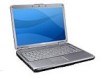
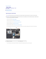
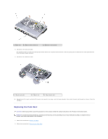
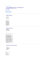
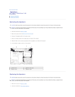
Back to Contents Page Palm Rest Dell™ Inspiron™ 1420/Dell Vostro™ 1400 Service Manual Removing the Palm Rest Replacing the Palm Rest Removing the Palm Rest CAUTION: Before you perform any of the procedures in this section, follow the safety instructions in the Product Information Guide. NOTICE: To avoid electrostatic discharge, ground yourself by using a wrist grounding strap or by periodically touching an unpainted metal surface, such as the back panel on the computer. 1. Follow the instructions in Before You Begin. 2. Remove the optical drive (see Removing the Optical Drive). 3. Remove the keyboard cover (see Removing the Keyboard Cover). 4. Remove the keyboard (see Removing the Keyboard). 5. Remove the display assembly (see Removing the Display Assembly). 6. Turn the computer over and remove all the screws (22) from the bottom of the computer including the three screws from the battery bay. 1 bottom of the system 2 screw (22) 7. Turn the computer over and remove the three M2.5 x 5mm screws from locations marked P on top of the palmrest.
-
 1
1 -
2
-
3
-
4
-
5
-
6
-
7
-
8
-
9
-
10
-
11
-
12
-
13
-
14
-
15
-
16
-
17
-
18
-
19
-
20
-
21
-
22
-
23
-
24
-
25
-
26
-
27
-
28
-
29
-
30
-
 31
31 -
 32
32 -
 33
33 -
 34
34 -
 35
35 -
 36
36 -
 37
37 -
 38
38 -
 39
39 -
 40
40 -
 41
41 -
42
-
43
-
44
-
45
 |
 |