Dell Inspiron 1420 Service Manual - Page 38
Replacing the Display Assembly, Replacing the Keyboard, Replacing the Keyboard Cover, Replacing
 |
View all Dell Inspiron 1420 manuals
Add to My Manuals
Save this manual to your list of manuals |
Page 38 highlights
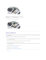
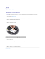
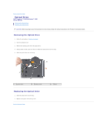
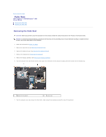
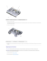
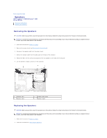
3. Align the new palm rest with the base of the computer, and then snap the palm rest into place. NOTICE: To prevent damage to the cables or the cable connectors, ensure that the locking clips on both sides of each system board connector are firmly seated and the cables are secure. 4. Connect the touch pad cable to the system board. 5. Connect the LED board cable to the system board. 6. Replace the three M2.5 x 5mm screws to the locations marked by letter P on top of the palmrest. 7. Turn the computer over and replace all the screws (22) in the bottom of the computer to secure the palm rest including the three screws in the battery bay. 8. Replace the display assembly (see Replacing the Display Assembly). 9. Replace the keyboard (see Replacing the Keyboard). 10. Replace the keyboard cover (see Replacing the Keyboard Cover). 11. Replace the optical drive (see Replacing the Optical Drive). Back to Contents Page
-
 1
1 -
2
-
3
-
4
-
5
-
6
-
7
-
8
-
9
-
10
-
11
-
12
-
13
-
14
-
15
-
16
-
17
-
18
-
19
-
20
-
21
-
22
-
23
-
24
-
25
-
26
-
27
-
28
-
29
-
30
-
31
-
32
-
 33
33 -
 34
34 -
 35
35 -
 36
36 -
 37
37 -
 38
38 -
 39
39 -
 40
40 -
 41
41 -
 42
42 -
 43
43 -
44
-
45
 |
 |
