Dell Inspiron 15 7537 Owners Manual - Page 35
Procedure, Lift the thermal-cooling assembly off the palm-rest assembly.
 |
View all Dell Inspiron 15 7537 manuals
Add to My Manuals
Save this manual to your list of manuals |
Page 35 highlights
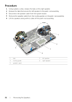
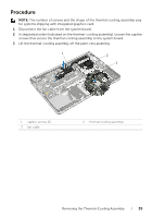
Procedure NOTE: The number of screws and the shape of the thermal-cooling assembly vary for systems shipping with integrated graphics card. 1 Disconnect the fan cable from the system board. 2 In sequential order (indicated on the thermal-cooling assembly), loosen the captive screws that secure the thermal-cooling assembly to the system board. 3 Lift the thermal-cooling assembly off the palm-rest assembly. 1 2 3 1 captive screws (5) 3 fan cable 2 thermal-cooling assembly Removing the Thermal-Cooling Assembly | 35
-
 1
1 -
2
-
3
-
4
-
5
-
6
-
7
-
8
-
9
-
10
-
11
-
12
-
13
-
14
-
15
-
16
-
17
-
18
-
19
-
20
-
21
-
22
-
23
-
24
-
25
-
26
-
27
-
28
-
29
-
 30
30 -
 31
31 -
 32
32 -
 33
33 -
 34
34 -
 35
35 -
 36
36 -
 37
37 -
 38
38 -
 39
39 -
 40
40 -
41
-
42
-
43
-
44
-
45
-
46
-
47
-
48
-
49
-
50
-
51
-
52
-
53
-
54
-
55
-
56
-
57
-
58
-
59
-
60
-
61
-
62
-
63
-
64
-
65
-
66
-
67
-
68
-
69
-
70
-
71
 |
 |

Removing the Thermal-Cooling Assembly
|
35
Procedure
NOTE:
The number of screws and the shape of the thermal-cooling assembly vary
for systems shipping with integrated graphics card.
1
Disconnect the fan cable from the system board.
2
In sequential order (indicated on the thermal-cooling assembly), loosen the captive
screws that secure the thermal-cooling assembly to the system board.
3
Lift the thermal-cooling assembly off the palm-rest assembly.
1
captive screws (5)
2
thermal-cooling assembly
3
fan cable
1
2
3