Dell Inspiron 1520 Service Manual - Page 29
Camera and Microphone Assembly
 |
View all Dell Inspiron 1520 manuals
Add to My Manuals
Save this manual to your list of manuals |
Page 29 highlights
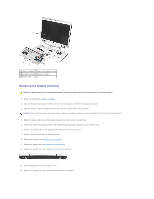
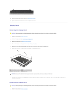
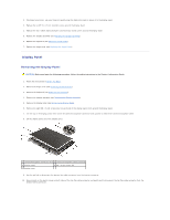
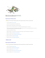
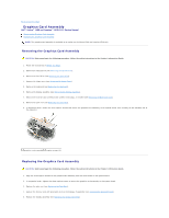
6. Using your fingers, carefully pull or flex the left side of display latch toward the bottom of the display cover (toward the hinges), and then lift to separate the latch from the cover. NOTICE: The display latch spring may be covered by a plastic sleeve. Neither the spring nor the plastic sleeve are secured to the latch assembly and can be easily misplaced. When removing the display latch, place the spring and plastic sleeve in a secure location. 7. Remove the display latch spring and set it aside. 1 display latch 2 display latch spring Replacing the Display Latch CAUTION: Before you begin the following procedure, follow the safety instructions in the Product Information Guide. 1. Follow the instructions in Before You Begin. 2. Slide the latch spring into the plastic sleeve, if present, then connect the spring to the display latch and display cover. 3. Align the notches on the display latch with the tabs on the display cover, then gently press the display latch into place. NOTE: If necessary, carefully pull or flex each end of the display latch toward the bottom of the display cover, and then press the latch into place. 4. Replace the display bezel (see Replacing the Display Bezel). 5. Replace the display assembly (see Replacing the Display Assembly). 6. Replace the keyboard (see Replacing the Keyboard). 7. Replace the hinge cover (see Replacing the Hinge Cover). Camera and Microphone Assembly Removing the Camera and Microphone Assembly CAUTION: Before you begin the following procedure, follow the safety instructions in the Product Information Guide. 1. Follow the instructions in Before You Begin. 2. Remove the hinge cover (see Removing the Hinge Cover). 3. Remove the keyboard (see Removing the Keyboard).
-
 1
1 -
2
-
3
-
4
-
5
-
6
-
7
-
8
-
9
-
10
-
11
-
12
-
13
-
14
-
15
-
16
-
17
-
18
-
19
-
20
-
21
-
22
-
23
-
 24
24 -
 25
25 -
 26
26 -
 27
27 -
 28
28 -
 29
29 -
 30
30 -
 31
31 -
 32
32 -
 33
33 -
 34
34 -
35
-
36
-
37
-
38
-
39
-
40
-
41
-
42
-
43
-
44
-
45
-
46
-
47
-
48
-
49
-
50
-
51
-
52
-
53
-
54
-
55
-
56
-
57
-
58
-
59
-
60
-
61
-
62
-
63
-
64
-
65
-
66
 |
 |
