Dell Inspiron 3655 desktop Inspiron 3655 Service Manual - Page 76
Clearing CMOS Settings, Prerequisites, Procedure
 |
View all Dell Inspiron 3655 desktop manuals
Add to My Manuals
Save this manual to your list of manuals |
Page 76 highlights
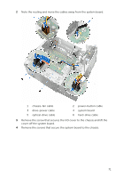
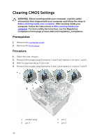
Clearing CMOS Settings WARNING: Before working inside your computer, read the safety information that shipped with your computer and follow the steps in Before working inside your computer. After working inside your computer, follow the instructions in After working inside your computer. For more safety best practices, see the Regulatory Compliance home page at www.dell.com/regulatory_compliance. Prerequisites 1 Remove the computer cover. 2 Remove the front bezel. Procedure 1 Open the side-chassis. 2 Remove the jumper plug from pins 2 and 3 and replace it on pins 1 and 2. 3 Wait for approximately 5 seconds. 4 Remove the jumper plug from pins 1 and 2 and replace it on pins 2 and 3. 1 jumper plug 3 pin 2 76 2 pin 1 4 pin 3
-
 1
1 -
2
-
3
-
4
-
5
-
6
-
7
-
8
-
9
-
10
-
11
-
12
-
13
-
14
-
15
-
16
-
17
-
18
-
19
-
20
-
21
-
22
-
23
-
24
-
25
-
26
-
27
-
28
-
29
-
30
-
31
-
32
-
33
-
34
-
35
-
36
-
37
-
38
-
39
-
40
-
41
-
42
-
43
-
44
-
45
-
46
-
47
-
48
-
49
-
50
-
51
-
52
-
53
-
54
-
55
-
56
-
57
-
58
-
59
-
60
-
61
-
62
-
63
-
64
-
65
-
66
-
67
-
68
-
69
-
70
-
 71
71 -
 72
72 -
 73
73 -
 74
74 -
 75
75 -
 76
76 -
 77
77 -
 78
78 -
 79
79 -
 80
80
 |
 |

Clearing CMOS Settings
WARNING: Before working inside your computer, read the safety
information that shipped with your computer and follow the steps in
Before working inside your computer
. After working inside your
computer, follow the instructions in
After working inside your
computer
. For more safety best practices, see the Regulatory
Compliance home page at www.dell.com/regulatory_compliance.
Prerequisites
1
Remove the
computer cover
.
2
Remove the
front bezel
.
Procedure
1
Open the side-chassis.
2
Remove the jumper plug from pins 2 and 3 and replace it on pins 1 and 2.
3
Wait for approximately 5 seconds.
4
Remove the jumper plug from pins 1 and 2 and replace it on pins 2 and 3.
1
jumper plug
2
pin 1
3
pin 2
4
pin 3
76