Dell Inspiron 5391 Service Manual - Page 47
Display bezel, Removing the display bezel
 |
View all Dell Inspiron 5391 manuals
Add to My Manuals
Save this manual to your list of manuals |
Page 47 highlights
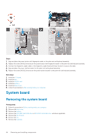
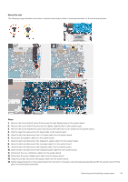
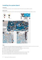
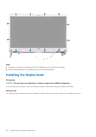
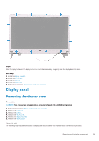
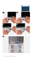
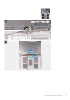
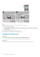
9. Connect the fingerprint-reader cable to the system board and close the latch to secure the cable. 10. Connect the speaker cable to the system board. 11. Connect the I/O-board cable to the system board and close the latch to secure the cable. 12. Adhere the tape that secures the I/O-board cable to the system board. 13. Replace the screw (M2x4) screw that secures the right display hinge to the system board. 14. Replace the screw (M2x4) that secures the display-cable bracket to the system board. 15. Replace the screw (M2.5x3.5) screw that secures the USB Type-C port bracket to the system board. Next steps 1. Install the power-adapter port. 2. Install the display assembly. 3. Install the heat sink. 4. Install the fan. 5. Install the WLAN card. 6. Install the M.2 2280 solid-state drive or M.2 2230 solid-state drive, whichever applicable. 7. Install the battery. 8. Install the base cover. 9. Follow the procedure in After working inside your computer. Display bezel Removing the display bezel Prerequisites NOTE: This procedure is not applicable to computers shipped with a WWAN configuration. 1. Follow the procedure in Before working inside your computer. 2. Remove the base cover. 3. Remove the battery. 4. Remove the WLAN card. 5. Remove the display assembly. About this task The following image indicates the location of display bezel and provides a visual representation of the removal procedure. Removing and installing components 47
-
 1
1 -
2
-
3
-
4
-
5
-
6
-
7
-
8
-
9
-
10
-
11
-
12
-
13
-
14
-
15
-
16
-
17
-
18
-
19
-
20
-
21
-
22
-
23
-
24
-
25
-
26
-
27
-
28
-
29
-
30
-
31
-
32
-
33
-
34
-
35
-
36
-
37
-
38
-
39
-
40
-
41
-
 42
42 -
 43
43 -
 44
44 -
 45
45 -
 46
46 -
 47
47 -
 48
48 -
 49
49 -
 50
50 -
 51
51 -
 52
52 -
53
-
54
-
55
-
56
-
57
-
58
-
59
-
60
-
61
-
62
-
63
-
64
-
65
-
66
-
67
-
68
-
69
-
70
-
71
-
72
-
73
-
74
-
75
-
76
-
77
-
78
-
79
-
80
-
81
 |
 |
