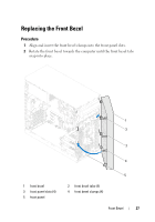
Dell Inspiron 660 Owners Manual - Page 22
Replacing the Memory Modules - upgrades
 |
View all Dell Inspiron 660 manuals
Add to My Manuals
Save this manual to your list of manuals |
Page 22 highlights
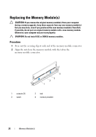
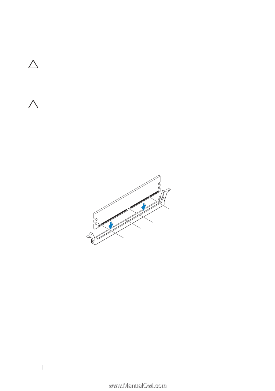
Replacing the Memory Module(s) CAUTION: If you remove the original memory module(s) from your computer during a memory upgrade, keep them separate from any new memory module(s) that you may have, even if you purchased the new memory module(s) from Dell. If possible, do not pair an original memory module with a new memory module. Otherwise, your computer may not start properly. CAUTION: Do not install ECC or DDR3U memory modules. Procedure 1 Press out the securing clip at each end of the memory module connector. 2 Align the notch on the memory module with the tab in the memory module connector. 1 cutouts (2) 3 notch 4 3 2 1 2 tab 4 memory module 22 Memory Module(s)
-
 1
1 -
2
-
3
-
4
-
5
-
6
-
7
-
8
-
9
-
10
-
11
-
12
-
13
-
14
-
15
-
16
-
 17
17 -
 18
18 -
 19
19 -
 20
20 -
 21
21 -
 22
22 -
 23
23 -
 24
24 -
 25
25 -
 26
26 -
 27
27 -
28
-
29
-
30
-
31
-
32
-
33
-
34
-
35
-
36
-
37
-
38
-
39
-
40
-
41
-
42
-
43
-
44
-
45
-
46
-
47
-
48
-
49
-
50
-
51
-
52
-
53
-
54
-
55
-
56
-
57
-
58
-
59
-
60
-
61
-
62
-
63
-
64
-
65
-
66
-
67
-
68
-
69
-
70
-
71
-
72
-
73
-
74
-
75
-
76
-
77
-
78
-
79
-
80
-
81
-
82
-
83
-
84
-
85
-
86
-
87
-
88
-
89
-
90
-
91
-
92
-
93
-
94
-
95
-
96
-
97
-
98
-
99
-
100
-
101
-
102
-
103
-
104
-
105
-
106
-
107
-
108
-
109
-
110
 |
 |
22
Memory Module(s)
Replacing the Memory Module(s)
CAUTION:
If you remove the original memory module(s) from your computer
during a memory upgrade, keep them separate from any new memory module(s)
that you may have, even if you purchased the new memory module(s) from Dell.
If possible, do not pair an original memory module with a new memory module.
Otherwise, your computer may not start properly.
CAUTION:
Do not install ECC or DDR3U memory modules.
Procedure
1
Press out the securing clip at each end of the memory module connector.
2
Align the notch on the memory module with the tab in the
memory module connector.
1
cutouts (2)
2
tab
3
notch
4
memory module
4
3
1
2