Dell Inspiron 660 Owners Manual - Page 58
AUDIOF1, USBF1, and USBF2. See System Board Components
 |
View all Dell Inspiron 660 manuals
Add to My Manuals
Save this manual to your list of manuals |
Page 58 highlights
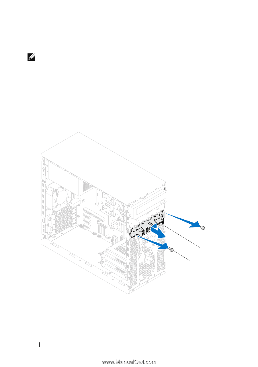
Procedure NOTE: Make note of the routing of all cables as you remove them so that you can re-route them correctly when installing the new front I/O panel. 1 Disconnect the front I/O panel cables from the system board connectors (AUDIOF1, USBF1, and USBF2). See "System Board Components" on page 14. 2 Remove the screws that secure the front I/O panel to the front panel. 3 Slide the front I/O panel towards the side as shown in the illustration to release the clamps from the front panel and pull it away. 1 screws (2) 58 Front I/O Panel 2 1 2 front I/O panel
-
 1
1 -
2
-
3
-
4
-
5
-
6
-
7
-
8
-
9
-
10
-
11
-
12
-
13
-
14
-
15
-
16
-
17
-
18
-
19
-
20
-
21
-
22
-
23
-
24
-
25
-
26
-
27
-
28
-
29
-
30
-
31
-
32
-
33
-
34
-
35
-
36
-
37
-
38
-
39
-
40
-
41
-
42
-
43
-
44
-
45
-
46
-
47
-
48
-
49
-
50
-
51
-
52
-
 53
53 -
 54
54 -
 55
55 -
 56
56 -
 57
57 -
 58
58 -
 59
59 -
 60
60 -
 61
61 -
 62
62 -
 63
63 -
64
-
65
-
66
-
67
-
68
-
69
-
70
-
71
-
72
-
73
-
74
-
75
-
76
-
77
-
78
-
79
-
80
-
81
-
82
-
83
-
84
-
85
-
86
-
87
-
88
-
89
-
90
-
91
-
92
-
93
-
94
-
95
-
96
-
97
-
98
-
99
-
100
-
101
-
102
-
103
-
104
-
105
-
106
-
107
-
108
-
109
-
110
 |
 |
58
Front I/O Panel
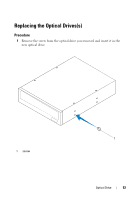
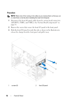
Procedure
NOTE:
Make note of the routing of all cables as you remove them so that you can
re-route them correctly when installing the new front I/O panel.
1
Disconnect the front I/O panel cables from the system board connectors
(AUDIOF1, USBF1, and USBF2). See "System Board Components" on
page 14.
2
Remove the screws that secure the front I/O panel to the front panel.
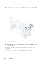
3
Slide the front I/O panel towards the side as shown in the illustration to
release the clamps from the front panel and pull it away.
1
screws (2)
2
front I/O panel
1
2