Dell Inspiron Mini 10v 1018 Inspiron Mini 1018 Service Manual - Page 43
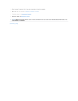
System Board
 |
View all Dell Inspiron Mini 10v 1018 manuals
Add to My Manuals
Save this manual to your list of manuals |
Page 43 highlights
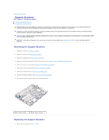
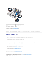
Back to Contents Page System Board Dell™ Inspiron™ 1018 Service Manual Removing the System Board Replacing the System Board Entering the Service Tag in the BIOS WARNING: Before working inside your computer, read the safety information that shipped with your computer. For additional safety best practices information, see the Regulatory Compliance Homepage at www.dell.com/regulatory_compliance. CAUTION: To avoid electrostatic discharge, ground yourself by using a wrist grounding strap or by periodically touching an unpainted metal surface (such as a connector on your computer). CAUTION: Only a certified service technician should perform repairs on your computer. Damage due to servicing that is not authorized by Dell™ is not covered by your warranty. CAUTION: To help prevent damage to the system board, remove the main battery (see Removing the Battery) before working inside the computer. CAUTION: Handle components and cards by their edges, and avoid touching pins and contacts. Removing the System Board 1. Follow the instructions in Before You Begin. 2. Remove any installed card or blank from the Media Card reader slot. 3. Remove the battery (see Removing the Battery). 4. Remove the keyboard (see Removing the Keyboard). 5. Remove the hard-drive assembly (follow the instructions from step 4 to step 6 in Removing the Hard Drive). 6. Remove the palm rest assembly (see Removing the Palm Rest Assembly). 7. Remove the memory module (see Removing the Memory Module). 8. Remove the Mini-Card (see Removing the Mini-Card). 9. Remove the middle cover (see Removing the Middle Cover). 10. Remove the display assembly (see Removing the Display Assembly). 11. Remove the support brackets (see Removing the Support Brackets). 12. Disconnect the AC adapter connector cable, status lights board cable, and I/O board cable from their connectors on the system board. 13. Remove the grounding screw that secures the I/O board cable to the system board.
-
 1
1 -
2
-
3
-
4
-
5
-
6
-
7
-
8
-
9
-
10
-
11
-
12
-
13
-
14
-
15
-
16
-
17
-
18
-
19
-
20
-
21
-
22
-
23
-
24
-
25
-
26
-
27
-
28
-
29
-
30
-
31
-
32
-
33
-
34
-
35
-
36
-
37
-
 38
38 -
 39
39 -
 40
40 -
 41
41 -
 42
42 -
 43
43 -
 44
44 -
 45
45 -
 46
46
 |
 |