Dell Latitude 3450 Dell Owners Manual - Page 36
Installing the Camera, Removing the System Board - touchpad
 |
View all Dell Latitude 3450 manuals
Add to My Manuals
Save this manual to your list of manuals |
Page 36 highlights
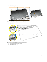
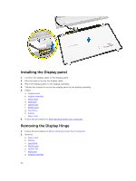
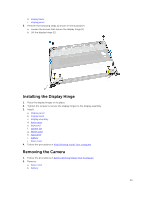
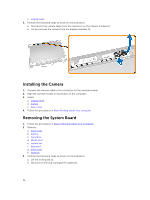
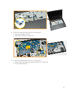
c. display bezel 3. Perform the following steps as shown in the illustration: a. Disconnect the camera cable from the connector on the camera module [1] b. Lift and remove the camera from the display assembly [2]. Installing the Camera 1. Connect the camera cable to the connector on the camera module. 2. Align the camera module in its position on the computer. 3. Install: a. display bezel b. battery c. base cover 4. Follow the procedures in After Working Inside Your computer. Removing the System Board 1. Follow the procedures in Before Working Inside Your Computer. 2. Remove: a. base cover b. battery c. hard drive d. WLAN card e. system fan f. keyboard g. back cover h. heatsink 3. Perform the following steps as shown in the illustration: a. Lift the locking tab [1]. b. Disconnect LED and touchpad the cables [2]. 36
-
 1
1 -
2
-
3
-
4
-
5
-
6
-
7
-
8
-
9
-
10
-
11
-
12
-
13
-
14
-
15
-
16
-
17
-
18
-
19
-
20
-
21
-
22
-
23
-
24
-
25
-
26
-
27
-
28
-
29
-
30
-
 31
31 -
 32
32 -
 33
33 -
 34
34 -
 35
35 -
 36
36 -
 37
37 -
 38
38 -
 39
39 -
 40
40 -
 41
41 -
42
-
43
-
44
-
45
-
46
-
47
-
48
-
49
-
50
-
51
-
52
-
53
-
54
-
55
-
56
-
57
-
58
-
59
-
60
-
61
 |
 |
