Dell Latitude 5400 Service Manual - Page 85
Installing the display assembly
 |
View all Dell Latitude 5400 manuals
Add to My Manuals
Save this manual to your list of manuals |
Page 85 highlights
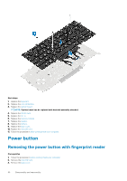
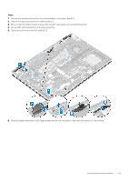
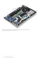
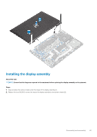
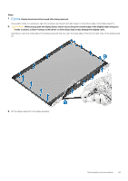
Installing the display assembly About this task NOTE: Ensure that the hinges are opened to the maximum before replacing the display assembly on the palmrest. Steps 1. Align and place the system chassis under the hinges of the display assembly [1]. 2. Replace the four (M2.5x5) screws that secure the display assembly to the system chassis [2]. Disassembly and reassembly 85
-
 1
1 -
2
-
3
-
4
-
5
-
6
-
7
-
8
-
9
-
10
-
11
-
12
-
13
-
14
-
15
-
16
-
17
-
18
-
19
-
20
-
21
-
22
-
23
-
24
-
25
-
26
-
27
-
28
-
29
-
30
-
31
-
32
-
33
-
34
-
35
-
36
-
37
-
38
-
39
-
40
-
41
-
42
-
43
-
44
-
45
-
46
-
47
-
48
-
49
-
50
-
51
-
52
-
53
-
54
-
55
-
56
-
57
-
58
-
59
-
60
-
61
-
62
-
63
-
64
-
65
-
66
-
67
-
68
-
69
-
70
-
71
-
72
-
73
-
74
-
75
-
76
-
77
-
78
-
79
-
 80
80 -
 81
81 -
 82
82 -
 83
83 -
 84
84 -
 85
85 -
 86
86 -
 87
87 -
 88
88 -
 89
89 -
 90
90 -
91
-
92
-
93
-
94
-
95
-
96
-
97
-
98
-
99
-
100
-
101
-
102
-
103
-
104
-
105
-
106
-
107
-
108
-
109
-
110
 |
 |

Installing the display assembly
About this task
NOTE:
Ensure that the hinges are opened to the maximum before replacing the display assembly on the palmrest.
Steps
1.
Align and place the system chassis under the hinges of the display assembly [1].
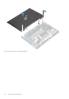
2.
Replace the four (M2.5x5) screws that secure the display assembly to the system chassis [2].
Disassembly and reassembly
85