Dell Latitude CP Service Manual - Page 5

Deohv - battery module

Page 5 highlights

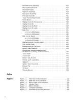
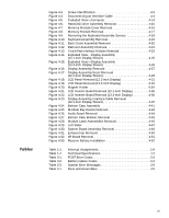
Figure 4-3. Figure 4-4. Figure 4-5. Figure 4-6. Figure 4-7. Figure 4-8. Figure 4-9. Figure 4-10. Figure 4-11. Figure 4-12. Figure 4-13. Figure 4-14. Figure 4-15. Figure 4-16. Figure 4-17. Figure 4-18. Figure 4-19. Figure 4-20. Figure 4-21. Figure 4-22. Figure 4-23. Figure 4-24. Figure 4-25. Figure 4-26. Figure 4-27. Figure 4-28. Figure 4-29. Figure 4-30. Figure 4-31. Figure 4-32. Figure 4-33. Screw Identification 4-3 Disconnecting an Interface Cable 4-4 Exploded View-Computer 4-14 Hard-Disk Drive Assembly Removal 4-15 Memory Module Cover Removal 4-16 Memory Module Removal 4-17 Removing the Keyboard Assembly Screws 4-18 Keyboard Assembly Removal 4-19 Back Cover Assembly Removal 4-20 Palmrest Assembly Removal 4-21 Touch-Pad Interface Module Removal 4-23 Exploded View-Display Assembly (12.1-Inch Display Shown 4-25 Exploded View-Display Assembly (13.3-Inch Display Shown 4-26 Display Assembly Removal 4-27 Display Assembly Bezel Removal (12.1-Inch Display Shown 4-29 LCD Panel Removal (12.1-Inch Display 4-31 LCD Panel Removal (13.3-Inch Display 4-32 Magnet Holder 4-34 LCD Inverter Board Removal (12.1-Inch Display 4-35 LCD Inverter Board Removal (13.3-Inch Display 4-36 Display-Assembly Interface Cable Removal (12.1-Inch Display Shown 4-37 Bottom Case Assembly 4-41 Modular Bay Device Removal 4-42 Audio Board Removal 4-44 Bottom Case Bracket Removal 4-45 Module Latch Assemblies Removal 4-46 Left Slider 4-47 System Board Assembly Removal 4-48 Exhaust Fan Removal 4-50 I/R Board Removal 4-51 Reserve Battery Installation 4-52 Table 1-1. Table 1-2. Table 3-1. Table 3-2. Table 3-3. Table 4-1. Interrupt Assignments 1-6 Technical Specifications 1-7 POST Error Codes 3-2 Battery Failure Codes 3-4 System Error Messages 3-5 Parts and Assemblies 4-5 vii

  • 1
  • 2
  • 3
  • 4
  • 5
  • 6
  • 7
  • 8
  • 9
  • 10
  • 11
  • 12
  • 13
  • 14
  • 15
  • 16
  • 17
  • 18
  • 19
  • 20
  • 21
  • 22
  • 23
  • 24
  • 25
  • 26
  • 27
  • 28
  • 29
  • 30
  • 31
  • 32
  • 33
  • 34
  • 35
  • 36
  • 37
  • 38
  • 39
  • 40
  • 41
  • 42
  • 43
  • 44
  • 45
  • 46
  • 47
  • 48
  • 49
  • 50
  • 51
  • 52
  • 53
  • 54
  • 55
  • 56
  • 57
  • 58
  • 59
  • 60
  • 61
  • 62
  • 63
  • 64
  • 65
  • 66
  • 67
  • 68
  • 69
  • 70
  • 71
  • 72
  • 73
  • 74
  • 75
  • 76
  • 77
  • 78
  • 79
  • 80
  • 81
  • 82
  • 83
  • 84
  • 85
  • 86
  • 87
  • 88
  • 89
  • 90
  • 91
  • 92
  • 93

vii
Figure 4-3.
Screw Identification. . . . . . . . . . . . . . . . . . . . . . . . . . . . . . . . . 4-3
Figure 4-4.
Disconnecting an Interface Cable . . . . . . . . . . . . . . . . . . . . . . 4-4
Figure 4-5.
Exploded View—Computer. . . . . . . . . . . . . . . . . . . . . . . . . . 4-14
Figure 4-6.
Hard-Disk Drive Assembly Removal . . . . . . . . . . . . . . . . . . . 4-15
Figure 4-7.
Memory Module Cover Removal . . . . . . . . . . . . . . . . . . . . . 4-16
Figure 4-8.
Memory Module Removal. . . . . . . . . . . . . . . . . . . . . . . . . . . 4-17
Figure 4-9.
Removing the Keyboard Assembly Screws . . . . . . . . . . . . . 4-18
Figure 4-10.
Keyboard Assembly Removal . . . . . . . . . . . . . . . . . . . . . . . . 4-19
Figure 4-11.
Back Cover Assembly Removal . . . . . . . . . . . . . . . . . . . . . . 4-20
Figure 4-12.
Palmrest Assembly Removal . . . . . . . . . . . . . . . . . . . . . . . . 4-21
Figure 4-13.
Touch-Pad Interface Module Removal . . . . . . . . . . . . . . . . . 4-23
Figure 4-14.
Exploded View—Display Assembly
(12.1-Inch Display Shown)
. . . . . . . . . . . . . . . . . . . . . . . . . . 4-25
Figure 4-15.
Exploded View—Display Assembly
(13.3-Inch Display Shown)
. . . . . . . . . . . . . . . . . . . . . . . . . . 4-26
Figure 4-16.
Display Assembly Removal. . . . . . . . . . . . . . . . . . . . . . . . . . 4-27
Figure 4-17.
Display Assembly Bezel Removal
(12.1-Inch Display Shown). . . . . . . . . . . . . . . . . . . . . . . . . . . 4-29
Figure 4-18.
LCD Panel Removal (12.1-Inch Display) . . . . . . . . . . . . . . . . 4-31
Figure 4-19.
LCD Panel Removal (13.3-Inch Display) . . . . . . . . . . . . . . . . 4-32
Figure 4-20.
Magnet Holder . . . . . . . . . . . . . . . . . . . . . . . . . . . . . . . . . . . 4-34
Figure 4-21.
LCD Inverter Board Removal (12.1-Inch Display) . . . . . . . . . 4-35
Figure 4-22.
LCD Inverter Board Removal (13.3-Inch Display) . . . . . . . . . 4-36
Figure 4-23.
Display-Assembly Interface Cable Removal
(12.1-Inch Display Shown). . . . . . . . . . . . . . . . . . . . . . . . . . . 4-37
Figure 4-24.
Bottom Case Assembly
. . . . . . . . . . . . . . . . . . . . . . . . . . . . 4-41
Figure 4-25.
Modular Bay Device Removal . . . . . . . . . . . . . . . . . . . . . . . . 4-42
Figure 4-26.
Audio Board Removal . . . . . . . . . . . . . . . . . . . . . . . . . . . . . . 4-44
Figure 4-27.
Bottom Case Bracket Removal
. . . . . . . . . . . . . . . . . . . . . . 4-45
Figure 4-28.
Module Latch Assemblies Removal . . . . . . . . . . . . . . . . . . . 4-46
Figure 4-29.
Left Slider . . . . . . . . . . . . . . . . . . . . . . . . . . . . . . . . . . . . . . . 4-47
Figure 4-30.
System Board Assembly Removal . . . . . . . . . . . . . . . . . . . . 4-48
Figure 4-31.
Exhaust Fan Removal . . . . . . . . . . . . . . . . . . . . . . . . . . . . . . 4-50
Figure 4-32.
I/R Board Removal. . . . . . . . . . . . . . . . . . . . . . . . . . . . . . . . . 4-51
Figure 4-33.
Reserve Battery Installation . . . . . . . . . . . . . . . . . . . . . . . . . 4-52
7DEOHV
Table 1-1.
Interrupt Assignments. . . . . . . . . . . . . . . . . . . . . . . . . . . . . . . 1-6
Table 1-2.
Technical Specifications
. . . . . . . . . . . . . . . . . . . . . . . . . . . . . 1-7
Table 3-1.
POST Error Codes
. . . . . . . . . . . . . . . . . . . . . . . . . . . . . . . . . 3-2
Table 3-2.
Battery Failure Codes . . . . . . . . . . . . . . . . . . . . . . . . . . . . . . . 3-4
Table 3-3.
System Error Messages . . . . . . . . . . . . . . . . . . . . . . . . . . . . . 3-5
Table 4-1.
Parts and Assemblies . . . . . . . . . . . . . . . . . . . . . . . . . . . . . . . 4-5