Dell Latitude CP Service Manual - Page 75
priate badge to the new cover.
 |
View all Dell Latitude CP manuals
Add to My Manuals
Save this manual to your list of manuals |
Page 75 highlights
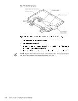
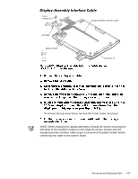
To remove a brace, remove the 3-mm screw securing the brace to the display-assembly top cover. NOTES: The replacement display-assembly top cover assembly includes two badges, one for Dell Latitude CP and one for the Dell Latitude CPi. Look at the old cover to determine which badge is appropriate, and then attach the appropriate badge to the new cover. When reinstalling the display assembly, install the four screws securing the hinges at the locations marked by arrows on the face of each hinge. Removing and Replacing Parts 4-39
-
 1
1 -
2
-
3
-
4
-
5
-
6
-
7
-
8
-
9
-
10
-
11
-
12
-
13
-
14
-
15
-
16
-
17
-
18
-
19
-
20
-
21
-
22
-
23
-
24
-
25
-
26
-
27
-
28
-
29
-
30
-
31
-
32
-
33
-
34
-
35
-
36
-
37
-
38
-
39
-
40
-
41
-
42
-
43
-
44
-
45
-
46
-
47
-
48
-
49
-
50
-
51
-
52
-
53
-
54
-
55
-
56
-
57
-
58
-
59
-
60
-
61
-
62
-
63
-
64
-
65
-
66
-
67
-
68
-
69
-
 70
70 -
 71
71 -
 72
72 -
 73
73 -
 74
74 -
 75
75 -
 76
76 -
 77
77 -
 78
78 -
 79
79 -
 80
80 -
81
-
82
-
83
-
84
-
85
-
86
-
87
-
88
-
89
-
90
-
91
-
92
-
93
 |
 |

Removing and Replacing Parts
4-39
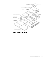
’LVSOD\´$VVHPEO\±7RS±&RYHU±
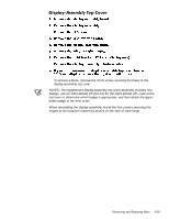
To remove a brace, remove the 3-mm screw securing the brace to the
display-assembly top cover.
NOTES: The replacement display-assembly top cover assembly includes two
badges, one for Dell Latitude CP and one for the Dell Latitude CPi. Look at the
old cover to determine which badge is appropriate, and then attach the appro-
priate badge to the new cover.
When reinstalling the display assembly, install the four screws securing the
hinges at the locations marked by arrows on the face of each hinge.