Dell Latitude CP Service Manual - Page 53
ory module with the corresponding key in the memory module socket.
 |
View all Dell Latitude CP manuals
Add to My Manuals
Save this manual to your list of manuals |
Page 53 highlights
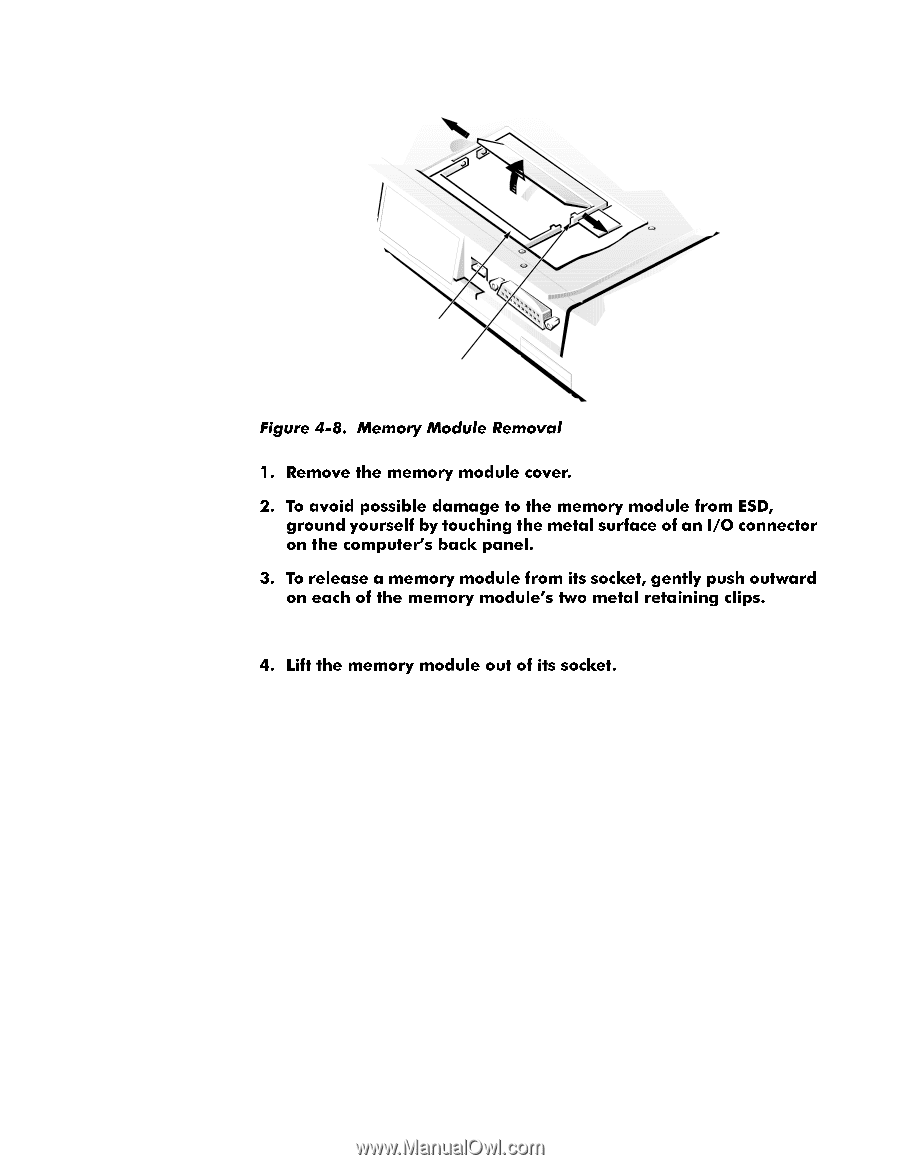
memory module sockets (2) retaining clips (2 per socket) The memory module should rotate upward out of its retaining clips. Memory modules can be installed only one way. Do not attempt to force the memory module into the socket. Align the notch near the center of the memory module with the corresponding key in the memory module socket. Removing and Replacing Parts 4-17
-
 1
1 -
2
-
3
-
4
-
5
-
6
-
7
-
8
-
9
-
10
-
11
-
12
-
13
-
14
-
15
-
16
-
17
-
18
-
19
-
20
-
21
-
22
-
23
-
24
-
25
-
26
-
27
-
28
-
29
-
30
-
31
-
32
-
33
-
34
-
35
-
36
-
37
-
38
-
39
-
40
-
41
-
42
-
43
-
44
-
45
-
46
-
47
-
 48
48 -
 49
49 -
 50
50 -
 51
51 -
 52
52 -
 53
53 -
 54
54 -
 55
55 -
 56
56 -
 57
57 -
 58
58 -
59
-
60
-
61
-
62
-
63
-
64
-
65
-
66
-
67
-
68
-
69
-
70
-
71
-
72
-
73
-
74
-
75
-
76
-
77
-
78
-
79
-
80
-
81
-
82
-
83
-
84
-
85
-
86
-
87
-
88
-
89
-
90
-
91
-
92
-
93
 |
 |
Removing and Replacing Parts
4-17
0HPRU\±0RGXOHV
The memory module should rotate upward out of its retaining clips.
Memory modules can be installed only one way. Do not attempt to force the
memory module into the socket. Align the notch near the center of the mem-
ory module with the corresponding key in the memory module socket.
memory module sockets (2)
retaining clips (2 per socket)