Dell Latitude E5250 Dell LatitudeE5250 / 5250 Owners Manual
Dell Latitude E5250 Manual
 |
View all Dell Latitude E5250 manuals
Add to My Manuals
Save this manual to your list of manuals |
Dell Latitude E5250 manual content summary:
- Dell Latitude E5250 | Dell LatitudeE5250 / 5250 Owners Manual - Page 1
Dell Latitude E5250 / 5250 Owner's Manual Regulatory Model: P25S Regulatory Type: P25S001 - Dell Latitude E5250 | Dell LatitudeE5250 / 5250 Owners Manual - Page 2
how to avoid the problem. WARNING: A WARNING indicates a potential for property damage, personal injury, or death. Copyright © 2014 Dell Inc. All rights reserved. This product is protected by U.S. and international copyright and intellectual property laws. Dell™ and the Dell logo are trademarks of - Dell Latitude E5250 | Dell LatitudeE5250 / 5250 Owners Manual - Page 3
only perform troubleshooting and simple repairs as authorized in your product documentation, or as directed by the online or telephone service and support team. Damage due to servicing that is not authorized by Dell is not covered by your warranty. Read and follow the safety instructions that came - Dell Latitude E5250 | Dell LatitudeE5250 / 5250 Owners Manual - Page 4
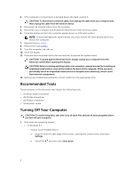
all open files and exit all open programs before you turn off your computer. 1. Shut down the operating system: • In Windows 8.1: - Using a touch-enabled device: a. Swipe in from the right edge of the screen, opening the Charms menu and select Settings. b. Select the and then select Shut down. 4 - Dell Latitude E5250 | Dell LatitudeE5250 / 5250 Owners Manual - Page 5
them off. After Working Inside Your Computer After you complete any replacement procedure, ensure you connect any external devices, cards, and cables before turning on your computer. CAUTION: To avoid damage to the computer, use only the battery designed for this particular Dell computer. Do not - Dell Latitude E5250 | Dell LatitudeE5250 / 5250 Owners Manual - Page 6
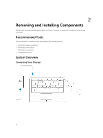
The procedures in this document may require the following tools: • Small flat-blade screwdriver • #0 Phillips screwdriver • #1 Phillips screwdriver • Small plastic scribe System Overview Connecting Your Charger 6 - Dell Latitude E5250 | Dell LatitudeE5250 / 5250 Owners Manual - Page 7
camera 7. power connector 9. power button 11. USB 3.0 connector with PowerShare 13. contactless smart-card reader (optional) 2. USB 3.0 connector 4. microphones (optional) 6. camera-status light 8. microphone 10. Mini-DisplayPort connector 12. memory-card reader 14. fingerprint reader (optional) 7 - Dell Latitude E5250 | Dell LatitudeE5250 / 5250 Owners Manual - Page 8
15. wireless-status light 17. hard-drive activity light 19. speakers 21. smart-card reader (optional) 23. security-cable slot 25. Service-Tag label 16. battery-status light 18. power-status light 20. touchpad 22. headset connector 24. dock connector (optional) Removing the SD Card 1. Follow the - Dell Latitude E5250 | Dell LatitudeE5250 / 5250 Owners Manual - Page 9
cover to the computer. 3. Follow the procedures in After Working Inside Your Computer. Removing the Battery 1. Follow the procedures in Before Working Inside Your Computer. 2. Remove the base cover. 3. Disconnect the battery cable from its connector [1] and release the cable from its routing channel - Dell Latitude E5250 | Dell LatitudeE5250 / 5250 Owners Manual - Page 10
1. Follow the procedure in Before Working Inside Your Computer. 2. Remove the: a. base cover b. battery 3. Perform the following steps: a. Disconnect the hard-drive cable from its connector on the system board [1] . b. Remove the screws that secure the hard-drive assembly to the computer [2]. 10 - Dell Latitude E5250 | Dell LatitudeE5250 / 5250 Owners Manual - Page 11
4. Remove the hard-drive assembly from the computer. 5. Pull to release the hard-drive cable from its connector. 11 - Dell Latitude E5250 | Dell LatitudeE5250 / 5250 Owners Manual - Page 12
the hard-drive bracket to the hard drive [1] and remove the hard drive from the hard-drive bracket [2]. Installing the Hard-Drive Assembly 1. Place the hard-drive bracket on the hard drive to align the screw holders and tighten the screws to secure the hard-drive bracket. 2. Connect the hard-drive - Dell Latitude E5250 | Dell LatitudeE5250 / 5250 Owners Manual - Page 13
-up and remove the memory from the system board. Installing the Memory 1. Insert the memory on the memory socket until the clips secure the memory. 2. Install the: a. battery b. base cover 3. Follow the procedures in After Working Inside Your Computer. Removing the Keyboard Trim 1. Follow the steps - Dell Latitude E5250 | Dell LatitudeE5250 / 5250 Owners Manual - Page 14
snaps in its place. 2. Follow the procedures in After Working Inside Your Computer. Removing the Keyboard 1. Follow the procedures in Before Working Inside Your Computer. 2. Remove the: a. base cover b. battery c. keyboard trim 3. Disconnect the keyboard cable from its connector on the system board - Dell Latitude E5250 | Dell LatitudeE5250 / 5250 Owners Manual - Page 15
holders on the computer. 2. Connect the keyboard cable to its connector on the system board. 3. Tighten the screws to secure the keyboard to the computer. 4. Install the: a. keyboard trim b. battery c. base cover 5. Follow the procedures in After Working Inside Your Computer. Removing the Palmrest - Dell Latitude E5250 | Dell LatitudeE5250 / 5250 Owners Manual - Page 16
a. base cover b. battery c. keyboard trim d. keyboard 3. Remove the screws that secure the palmrest to the computer. 4. Flip the computer and perform the following steps: a. Disconnect the touchpad cable and USH board cable from their connectors [1] [2]. b. Remove the screw that secures the palmrest - Dell Latitude E5250 | Dell LatitudeE5250 / 5250 Owners Manual - Page 17
the procedures in Before Working Inside Your Computer. 2. Remove the: a. base cover b. battery c. memory d. keyboard trim e. keyboard f. palmrest 3. Perform the following steps: a. Disconnect the SmartCard reader board cable from the USH board [1] [2]. b. Peel the cable to release from the adhesive - Dell Latitude E5250 | Dell LatitudeE5250 / 5250 Owners Manual - Page 18
4. Release the SmartCard reader board. To release the SmartCard reader board: a. Remove the screws that secure the SmartCard-reader board to the palmrest [1]. b. Push the SmartCard-reader board to release it [2]. 5. Remove the SmartCard reader board from the palmrest. 18 - Dell Latitude E5250 | Dell LatitudeE5250 / 5250 Owners Manual - Page 19
sold separately and is not shipped with the computer. 1. Follow the procedures in Before Working Inside Your Computer. 2. Remove the: a. base cover b. battery c. hard-drive assembly d. keyboard trim e. keyboard f. palmrest 3. Perform the following steps to remove the USH board: a. Disconnect all the - Dell Latitude E5250 | Dell LatitudeE5250 / 5250 Owners Manual - Page 20
all the cables to the USH board. 4. Install the: a. palmrest b. keyboard c. keyboard trim d. hard-drive assembly e. battery f. base cover 5. Follow the procedures in After Working Inside Your Computer. Removing the Finger-Print Reader Board NOTE: This component is sold separately and is not shipped - Dell Latitude E5250 | Dell LatitudeE5250 / 5250 Owners Manual - Page 21
Place the metal bracket on the finger-print reader board and tighten the screw to secure the finger- print reader board. 4. Install the: a. keyboard trim b. keyboard c. palmrest d. battery e. base cover 5. Follow the procedures in After Working Inside Your Computer. Removing the LED Board 1. Follow - Dell Latitude E5250 | Dell LatitudeE5250 / 5250 Owners Manual - Page 22
to the palmrest. 3. Connect the LED-board cable to its connector on the LED board. 4. Install the: a. palmrest b. keyboard c. keyboard trim d. battery e. base cover 5. Follow the procedures in After Working Inside Your Computer. Removing the Power-Connector Port 1. Follow the procedures in Before - Dell Latitude E5250 | Dell LatitudeE5250 / 5250 Owners Manual - Page 23
Perform the following steps: a. Flip the computer. b. Remove the screw to release the metal bracket on the power-connector port [1] [2]. c. Lift and remove its connector on the system board. 5. Install the: a. battery b. base cover 6. Follow the procedures in After Working Inside Your Computer. 23 - Dell Latitude E5250 | Dell LatitudeE5250 / 5250 Owners Manual - Page 24
Removing the WLAN Card 1. Follow the procedures in Before Working Inside Your Computer. 2. Remove the base cover. 3. Perform the following steps to remove the WLAN card: to their connectors on the WLAN Card. 4. Install the base cover. 5. Follow the procedures in After Working Inside Your Computer. 24 - Dell Latitude E5250 | Dell LatitudeE5250 / 5250 Owners Manual - Page 25
Removing the WWAN Card 1. Follow the procedures in Before Working Inside Your Computer. 2. Remove the base cover. 3. Perform the following steps to remove the WWAN card: to their connectors on the WWAN Card. 4. Install the base cover. 5. Follow the procedures in After Working Inside Your Computer. 25 - Dell Latitude E5250 | Dell LatitudeE5250 / 5250 Owners Manual - Page 26
Removing the Display-Hinge Brackets 1. Follow the procedures in Before Working Inside Your Computer. 2. Remove the: a. base cover b. battery c. memory d. hard-drive assembly e. keyboard trim f. keyboard g. palmrest 3. Remove the screws that secure the display-hinge brackets to the back of the - Dell Latitude E5250 | Dell LatitudeE5250 / 5250 Owners Manual - Page 27
of the computer to secure the display-hinge brackets. 3. Install the: a. palmrest b. keyboard c. keyboard trim d. hard-drive assembly e. memory f. battery g. base cover 4. Follow the procedures in After Working Inside Your Computer. Removing the Display Assembly 1. Follow the procedures in Before - Dell Latitude E5250 | Dell LatitudeE5250 / 5250 Owners Manual - Page 28
5. Release the display cable from its routing channel. 6. Remove the screws that secure the display assembly [1] and lift the display assembly to remove it from the computer [2]. 28 - Dell Latitude E5250 | Dell LatitudeE5250 / 5250 Owners Manual - Page 29
display-hinge brackets b. palmrest c. keyboard d. keyboard trim e. battery f. base cover 7. Follow the procedures in After Working Inside Your Computer. Removing the Display Bezel 1. Follow the procedures in Before Working Inside Your Computer. 2. Pry the edges to release the display bezel from the - Dell Latitude E5250 | Dell LatitudeE5250 / 5250 Owners Manual - Page 30
clicks on to the display assembly. 3. Follow the procedures in After Working Inside Your Computer. Removing the Display Panel 1. Follow the procedures in Before Working Inside Your Computer. 2. Remove the: a. base cover b. battery c. display bezel 3. Remove the screws that secure the display panel - Dell Latitude E5250 | Dell LatitudeE5250 / 5250 Owners Manual - Page 31
4. Peel the adhesive [1] to access the eDP cable [2]. 5. Disconnect the eDP cable from its connector [1] and remove the display panel from the display assembly [2]. 31 - Dell Latitude E5250 | Dell LatitudeE5250 / 5250 Owners Manual - Page 32
Your Computer. Removing the Display Hinges 1. Follow the procedures in Before Working Inside Your Computer. 2. Remove the: a. base cover b. battery c. memory d. hard-drive assembly e. keyboard trim f. keyboard g. palmrest h. display-hinge brackets i. display assembly j. display bezel 3. Perform the - Dell Latitude E5250 | Dell LatitudeE5250 / 5250 Owners Manual - Page 33
. 3. Install the: a. display bezel b. display assembly c. display-hinge brackets d. palmrest e. keyboard f. keyboard trim g. hard-drive assembly h. memory i. battery j. base cover 4. Follow the procedures in After Working Inside Your Computer. Removing the Camera 1. Follow the procedures in Before - Dell Latitude E5250 | Dell LatitudeE5250 / 5250 Owners Manual - Page 34
Your Computer. Removing the eDP Cable 1. Follow the procedures in Before Working Inside Your Computer. 2. Remove the: a. base cover b. battery c. memory d. hard-drive assembly e. keyboard trim f. keyboard g. palmrest h. display-hinge brackets i. display assembly j. display bezel k. display panel - Dell Latitude E5250 | Dell LatitudeE5250 / 5250 Owners Manual - Page 35
the: a. display panel b. display bezel c. display assembly d. display-hinge brackets e. palmrest f. keyboard g. keyboard trim h. hard-drive assembly i. memory j. battery k. base cover 4. Follow the procedures in After Working Inside Your Computer. Removing the System Fan 1. Follow the procedures in - Dell Latitude E5250 | Dell LatitudeE5250 / 5250 Owners Manual - Page 36
the screws to secure the system fan to the computer. 3. Connect the system-fan cable to its connector on the system board. 4. Install the: a. palmrest b. keyboard c. keyboard trim d. battery e. base cover 5. Follow the procedures in After Working Inside Your Computer. 36 - Dell Latitude E5250 | Dell LatitudeE5250 / 5250 Owners Manual - Page 37
procedures in Before Working Inside Your Computer. 2. Remove the: a. base cover b. battery c. memory d. hard-drive assembly e. keyboard trim f. keyboard g. palmrest 3. Perform the following steps to remove the coin-cell battery from the computer: a. Disconnect the coin-cell battery cable from its - Dell Latitude E5250 | Dell LatitudeE5250 / 5250 Owners Manual - Page 38
Working Inside Your Computer. 2. Remove the: a. SD card b. base cover c. battery d. memory e. hard-drive assembly f. keyboard trim g. keyboard [2] c. coin-cell battery [3] 4. Remove the screws that secure the system board to the chassis [1] and push the system board to release from its place. - Dell Latitude E5250 | Dell LatitudeE5250 / 5250 Owners Manual - Page 39
screws to secure the system board to the computer. 3. Connect the following cables to their connectors on the system board: a. speaker b. power-connector c. coin-cell battery 4. Install the: a. display assembly 39 - Dell Latitude E5250 | Dell LatitudeE5250 / 5250 Owners Manual - Page 40
b. display-hinge brackets c. palmrest d. keyboard e. keyboard trim f. hard-drive assembly g. memory h. battery i. base cover j. SD card 5. Follow the procedures in After Working Inside Your Computer. Removing the Heatsink 1. Follow the procedures in Before Working Inside Your Computer. 2. Remove the - Dell Latitude E5250 | Dell LatitudeE5250 / 5250 Owners Manual - Page 41
the: a. system board b. system fan c. display assembly d. display-hinge brackets e. palmrest f. keyboard g. keyboard trim h. hard-drive assembly i. memory j. battery k. base cover 4. Follow the procedures in After Working Inside Your Computer. Removing the Speakers 1. Follow the procedures in Before - Dell Latitude E5250 | Dell LatitudeE5250 / 5250 Owners Manual - Page 42
the speaker cable to its connector on the system board. 5. Install the: a. system fan b. display assembly c. display-hinge brackets d. palmrest e. keyboard f. keyboard trim g. hard-drive assembly h. memory i. battery j. base cover 6. Follow the procedures in After Working Inside Your Computer. 42 - Dell Latitude E5250 | Dell LatitudeE5250 / 5250 Owners Manual - Page 43
and 64-Bit Technology. • Device Information: Displays Primary Hard Drive, Dock eSATA Device, LOM MAC Address, Video Controller, Video BIOS Version, Video Memory, Panel Type, Native Resolution, Audio Controller, Wi-Fi Device, WiGig Device, Cellular Device, Bluetooth Device. Battery Information Boot - Dell Latitude E5250 | Dell LatitudeE5250 / 5250 Owners Manual - Page 44
Technology) specification. This option is disabled by default. • Enable SMART Reporting USB Configuration This field configures the integrated USB controller. If Boot Support is enabled, the system is allowed to boot any type of USB Mass Storage Devices (HDD, memory key, floppy). If USB port - Dell Latitude E5250 | Dell LatitudeE5250 / 5250 Owners Manual - Page 45
Boot Support • Enable External USB Port • Enable USB3.0 Controller NOTE: USB keyboard and mouse always work in the BIOS setup irrespective of these settings. This field configures the USB PowerShare feature behavior. This option allows you to charge external devices using the stored system battery - Dell Latitude E5250 | Dell LatitudeE5250 / 5250 Owners Manual - Page 46
up on the power source (On Battery and On AC). NOTE: The Video disable the permission to bypass the System and the Internal HDD password, when they are set. The options are: • Disabled • Reboot bypass Default Setting: Disabled Allows you to enable the disable permission to the System and Hard Drive - Dell Latitude E5250 | Dell LatitudeE5250 / 5250 Owners Manual - Page 47
changes will be allowed Deactivate (default) CPU XD Support Allows you to enable the Execute Disable mode of the processor. Enable CPU XD Support (default) OROM Keyboard Access Allows you to set an option to enter the Option ROM Configuration screens using hotkeys during boot. The options are - Dell Latitude E5250 | Dell LatitudeE5250 / 5250 Owners Manual - Page 48
Multi Core Support Intel SpeedStep C States Control Intel TurboBoost Hyper-Thread Control Description • KEK • db • dbx If you enable the Custom Mode, the relevant options for PK, KEK, db, and dbx appear. The options are: • Save to File- Saves the key to a user-selected file • Replace from File - Dell Latitude E5250 | Dell LatitudeE5250 / 5250 Owners Manual - Page 49
ports to conserve battery power. • Enable USB Wake Support Default Setting: The option is disabled. Allows you to enable or disable the feature that automatically switches from wired or wireless networks without depending on the physical connection. • Control WLAN Radio • Control WWAN Radio Default - Dell Latitude E5250 | Dell LatitudeE5250 / 5250 Owners Manual - Page 50
work hours to improve the battery health. Disabled (default) Allows you to select the charging mode for the battery. The options are: • Adaptive (Latitude E5250) • Standard - Fully charges your battery at a standard rate. • ExpressCharge - The battery charges over a shorter period of time using Dell - Dell Latitude E5250 | Dell LatitudeE5250 / 5250 Owners Manual - Page 51
selected by default. • Lock Mode Disable / Standard • Lock Mode Enable / Secondary MEBx Hotkey Fastboot Extended BIOS POST Time Allows you to specify seconds • 10 seconds Table 9. Virtualization Support Option Description Virtualization Allows you to enable or disable the Intel - Dell Latitude E5250 | Dell LatitudeE5250 / 5250 Owners Manual - Page 52
for direct I/O must be enabled to use this feature. Trusted Execution - disabled by default. Table 10. Wireless Option Wireless Switch Description Allows to set the wireless devices that can be controlled by the wireless switch. The options are: • WWAN • GPS (on WWAN Module) • WLAN/WiGig - Dell Latitude E5250 | Dell LatitudeE5250 / 5250 Owners Manual - Page 53
Table 14. Processor Feature Types L3 cache i3 i5 Celeron Specification Intel Celeron, Core i3/ i5 3 MB 3 MB 2 MB Table 15. Memory Feature Memory connector Latitude 5250 Latitude E5250 Memory capacity Memory type Minimum memory Maximum memory Specification One SODIMM slot Two SODIMM slots 4 GB - Dell Latitude E5250 | Dell LatitudeE5250 / 5250 Owners Manual - Page 54
memory in each available memory slots Table 16. Audio Feature Type Controller Stereo conversion Interface: Internal External Speakers Internal speaker amplifier Volume controls Table 17. Video Feature Type Controller: UMA Data bus External display support HD Graphics • i3, i5 Intel HD Graphics - Dell Latitude E5250 | Dell LatitudeE5250 / 5250 Owners Manual - Page 55
10/100/1000 Mb/s Ethernet (RJ-45) internal wireless local area network (WLAN) and wireless wide area network (WWAN). NOTE: WWAN is optional. Table 20. Ports and Connectors Features Audio Video Network adapter USB Memory card reader Micro Subscriber Identity Module (uSIM) card - optional Docking - Dell Latitude E5250 | Dell LatitudeE5250 / 5250 Owners Manual - Page 56
Backlit KB Non-Backlit KB United States: 106 keys, United Kingdom: 107 keys, Brazil: 109 keys, and Japan: 110 keys Table 24. Touchpad Feature Active Area: X-axis Y-axis Specification 99.50 mm 53.00 mm Table 25. Battery Feature E5250 Type 3-Cell (38 Whr) 4-Cell (51 Whr) Dimensions - Dell Latitude E5250 | Dell LatitudeE5250 / 5250 Owners Manual - Page 57
Width Depth Weight W/O Touch With Touch 20.50 Storage Altitude (maximum): Operating Specification 0 °C to 35 °C (32 °F to 95 °F) -40 °C to 65 °C (-40 °F to 149 °F) 10 % to 90 % (non condensing) 5 % to 95 % (non condensing) 0 m to 3048 m (0 ft to 10,000 ft) 0° to 35°C Non-Operating 0 m to 10 - Dell Latitude E5250 | Dell LatitudeE5250 / 5250 Owners Manual - Page 58
58 - Dell Latitude E5250 | Dell LatitudeE5250 / 5250 Owners Manual - Page 59
the computer. 2. As the computer boots, press the key as the Dell logo appears. 3. On the boot menu screen, select the Diagnostics option. The Enhanced Pre-boot System Assessment window displays, listing all devices detected in the computer. The diagnostics starts running the tests on all the - Dell Latitude E5250 | Dell LatitudeE5250 / 5250 Owners Manual - Page 60
. Turns on steadily or blinks to indicate battery charge status. Turns on when wireless networking is enabled. The device status LEDs are usually located either on the top or left side of the keyboard. They display the storage, battery and wireless devices connectivity and activity. Apart from that - Dell Latitude E5250 | Dell LatitudeE5250 / 5250 Owners Manual - Page 61
Storage LED Blinking Off Off Power LED Solid Blinking Blinking Wireless LED Blinking Blinking Off Fault Description The display encountered a problem during initialization. The modem is preventing the system from completing POST Memory failed to initialize or memory is unsupported. Battery - Dell Latitude E5250 | Dell LatitudeE5250 / 5250 Owners Manual - Page 62
options. Availability varies by country and product, and some services may not be available in your area. To contact Dell for sales, technical support, or customer service issues: 1. Go to dell.com/support. 2. Select your support category. 3. Verify your country or region in the Choose a Country
-
 1
1 -
 2
2 -
 3
3 -
 4
4 -
 5
5 -
 6
6 -
 7
7 -
8
-
9
-
10
-
11
-
12
-
13
-
14
-
15
-
16
-
17
-
18
-
19
-
20
-
21
-
22
-
23
-
24
-
25
-
26
-
27
-
28
-
29
-
30
-
31
-
32
-
33
-
34
-
35
-
36
-
37
-
38
-
39
-
40
-
41
-
42
-
43
-
44
-
45
-
46
-
47
-
48
-
49
-
50
-
51
-
52
-
53
-
54
-
55
-
56
-
57
-
58
-
59
-
60
-
61
-
62
 |
 |

Dell Latitude E5250 / 5250
Owner's Manual
Regulatory Model: P25S
Regulatory Type: P25S001