Dell Latitude E6400 Service Manual - Page 7
Battery Latch Assembly - memory
 |
View all Dell Latitude E6400 manuals
Add to My Manuals
Save this manual to your list of manuals |
Page 7 highlights
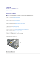
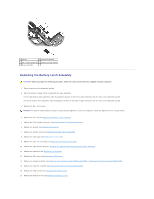
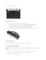
Back to Contents Page Battery Latch Assembly Dell™ Latitude™ E6400 and E6400 ATG and Mobile Workstation Precision™ M2400 Service Manual Removing a Battery Latch Assembly Replacing the Battery Latch Assembly There are two battery latches, a left and a right, and each latch uses a unique latch assembly. The spring, screw, and release buttons are the same for the left and right battery latches. The removing and replacing procedures are primarily the same for the right and the left battery latch. The differences are noted for the instructions that are different for the right and left battery latches. Removing a Battery Latch Assembly CAUTION: Before you begin the following procedure, follow the safety instructions that shipped with your computer. 1. Follow the instructions in Before Working on Your Computer. 2. Remove the bottom of the base assembly (see Removing the Bottom of the Base Assembly). 3. Remove the hard drive (see Removing the Hard Drive). 4. Remove the modular drive (see Removing the Modular Drive). 5. Remove the hinge covers (see Removing the Hinge Covers). 6. Remove the heatsink assembly (see Removing the Processor Heatsink Assembly). 7. Remove the display assembly (see Removing the Display Assembly (E6400 and M2400) or Removing the Display Assembly (E6400 ATG)). 8. Remove the LED cover (see Removing the LED Cover). 9. Remove the keyboard (see Removing the Keyboard). 10. Remove the right speaker grill (see Removing the Right Speaker Grill/Fingerprint Reader Assembly). 11. Remove the palm rest assembly (see Removing the Palm Rest Assembly). 12. Remove the card cage (see Removing the Card Cage). 13. Remove the system board (see Removing the System Board Assembly). Do not remove the wireless mini-cards, memory modules, or processor from the system board. 14. Remove the modem (see Removing the Modem). 15. Remove the RJ-11 modem connector (see Removing the RJ-11 Modem Connector). 16. Remove the I/O card (see Removing the I/O Card). 17. Remove the M2 x 3-mm screw from the alignment bracket, and remove the battery latch assembly. NOTICE: The spring is not secured to the alignment bracket and can be easily misplaced. When removing the battery latch assembly, place the spring in a secure location until the assembly is ready to be reinstalled. 18. Remove the spring from the alignment bracket and set it aside until the assembly is ready to be reinstalled.
-
 1
1 -
 2
2 -
 3
3 -
 4
4 -
 5
5 -
 6
6 -
 7
7 -
 8
8 -
 9
9 -
 10
10 -
 11
11 -
 12
12 -
13
-
14
-
15
-
16
-
17
-
18
-
19
-
20
-
21
-
22
-
23
-
24
-
25
-
26
-
27
-
28
-
29
-
30
-
31
-
32
-
33
-
34
-
35
-
36
-
37
-
38
-
39
-
40
-
41
-
42
-
43
-
44
-
45
-
46
-
47
-
48
-
49
-
50
-
51
-
52
-
53
-
54
-
55
-
56
-
57
-
58
-
59
-
60
-
61
-
62
-
63
-
64
-
65
-
66
-
67
-
68
-
69
-
70
-
71
-
72
-
73
-
74
-
75
-
76
-
77
-
78
-
79
-
80
-
81
-
82
-
83
-
84
-
85
-
86
-
87
-
88
-
89
-
90
-
91
-
92
-
93
-
94
-
95
-
96
-
97
-
98
-
99
 |
 |