Dell OptiPlex G1 Dell OptiPlex G1 Mini Tower Managed PC Systems Reference and - Page 102
Dell OptiPlex G1 Mini Tower Managed PC Reference and Installation Guide, DIMMs 2, sockets - optiplex 160 memory
 |
View all Dell OptiPlex G1 manuals
Add to My Manuals
Save this manual to your list of manuals |
Page 102 highlights
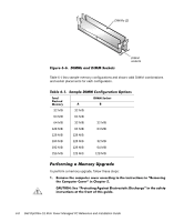
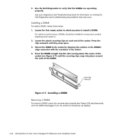
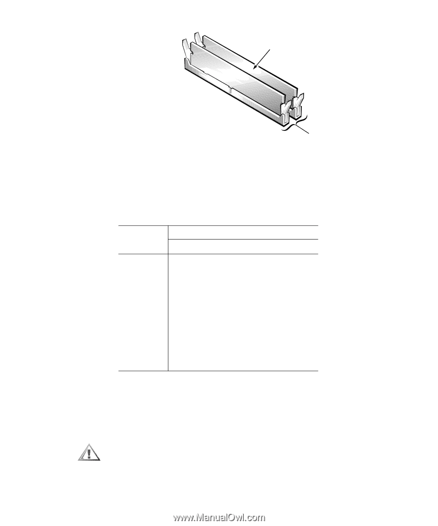
DIMMs (2) DIMM sockets Table 6-1 lists sample memory configurations and shows valid DIMM combinations and socket placements for each configuration. . 32 MB 64 MB 64 MB 128 MB 128 MB 160 MB 192 MB 256 MB 32 MB 64 MB 32 MB 64 MB 128 MB 128 MB 128 MB 128 MB 32 MB 64 MB 32 MB 64 MB 128 MB To perform a memory upgrade, follow these steps: 6-8 Dell OptiPlex G1 Mini Tower Managed PC Reference and Installation Guide
-
 1
1 -
2
-
3
-
4
-
5
-
6
-
7
-
8
-
9
-
10
-
11
-
12
-
13
-
14
-
15
-
16
-
17
-
18
-
19
-
20
-
21
-
22
-
23
-
24
-
25
-
26
-
27
-
28
-
29
-
30
-
31
-
32
-
33
-
34
-
35
-
36
-
37
-
38
-
39
-
40
-
41
-
42
-
43
-
44
-
45
-
46
-
47
-
48
-
49
-
50
-
51
-
52
-
53
-
54
-
55
-
56
-
57
-
58
-
59
-
60
-
61
-
62
-
63
-
64
-
65
-
66
-
67
-
68
-
69
-
70
-
71
-
72
-
73
-
74
-
75
-
76
-
77
-
78
-
79
-
80
-
81
-
82
-
83
-
84
-
85
-
86
-
87
-
88
-
89
-
90
-
91
-
92
-
93
-
94
-
95
-
96
-
 97
97 -
 98
98 -
 99
99 -
 100
100 -
 101
101 -
 102
102 -
 103
103 -
 104
104 -
 105
105 -
 106
106 -
 107
107 -
108
-
109
-
110
-
111
-
112
-
113
-
114
-
115
-
116
-
117
-
118
-
119
-
120
-
121
-
122
-
123
-
124
-
125
-
126
-
127
-
128
-
129
-
130
-
131
-
132
-
133
-
134
-
135
-
136
-
137
-
138
-
139
-
140
-
141
-
142
-
143
-
144
-
145
-
146
-
147
-
148
-
149
-
150
-
151
-
152
-
153
-
154
-
155
-
156
-
157
-
158
-
159
-
160
-
161
-
162
-
163
-
164
 |
 |
6-8
Dell OptiPlex G1 Mini Tower Managed PC Reference and Installation Guide
)LJXUH±»¶»µ±±’,00V±DQG±’,00±6RFNHWV
Table 6-1 lists sample memory configurations and shows valid DIMM combinations
and socket placements for each configuration.
.
3HUIRUPLQJ±D±0HPRU\±8SJUDGH
To perform a memory upgrade, follow these steps:
¹·
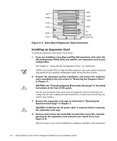
5HPRYH²WKH²FRPSXWHU²FRYHU²DFFRUGLQJ²WR²WKH²LQVWUXFWLRQV²LQ²¼5HPRYLQJ²
WKH²&RPSXWHU²&RYHUΜ²LQ²&KDSWHU²¸·
&$87,21±²6HH²¼3URWHFWLQJ²$JDLQVW²(OHFWURVWDWLF²’LVFKDUJHΜ²LQ²WKH²VDIHW\²
LQVWUXFWLRQV²DW²WKH²IURQW²RI²WKLV²JXLGH·
7DEOH±»¶´µ±±6DPSOH±’,00±&RQILJXUDWLRQ±2SWLRQV
7RWDO
’HVLUHG
0HPRU\
’,00²6RFNHW
²²²²²$
²²²²²%
32 MB
32 MB
64 MB
64 MB
64 MB
32 MB
32 MB
128 MB
64 MB
64 MB
128 MB
128 MB
160 MB
128 MB
32 MB
192 MB
128 MB
64 MB
256 MB
128 MB
128 MB
DIMMs (2)
DIMM
sockets