Dell OptiPlex G1 Dell OptiPlex G1 Mini Tower Managed PC Systems Reference and - Page 74
Microsoft Windows NT
 |
View all Dell OptiPlex G1 manuals
Add to My Manuals
Save this manual to your list of manuals |
Page 74 highlights
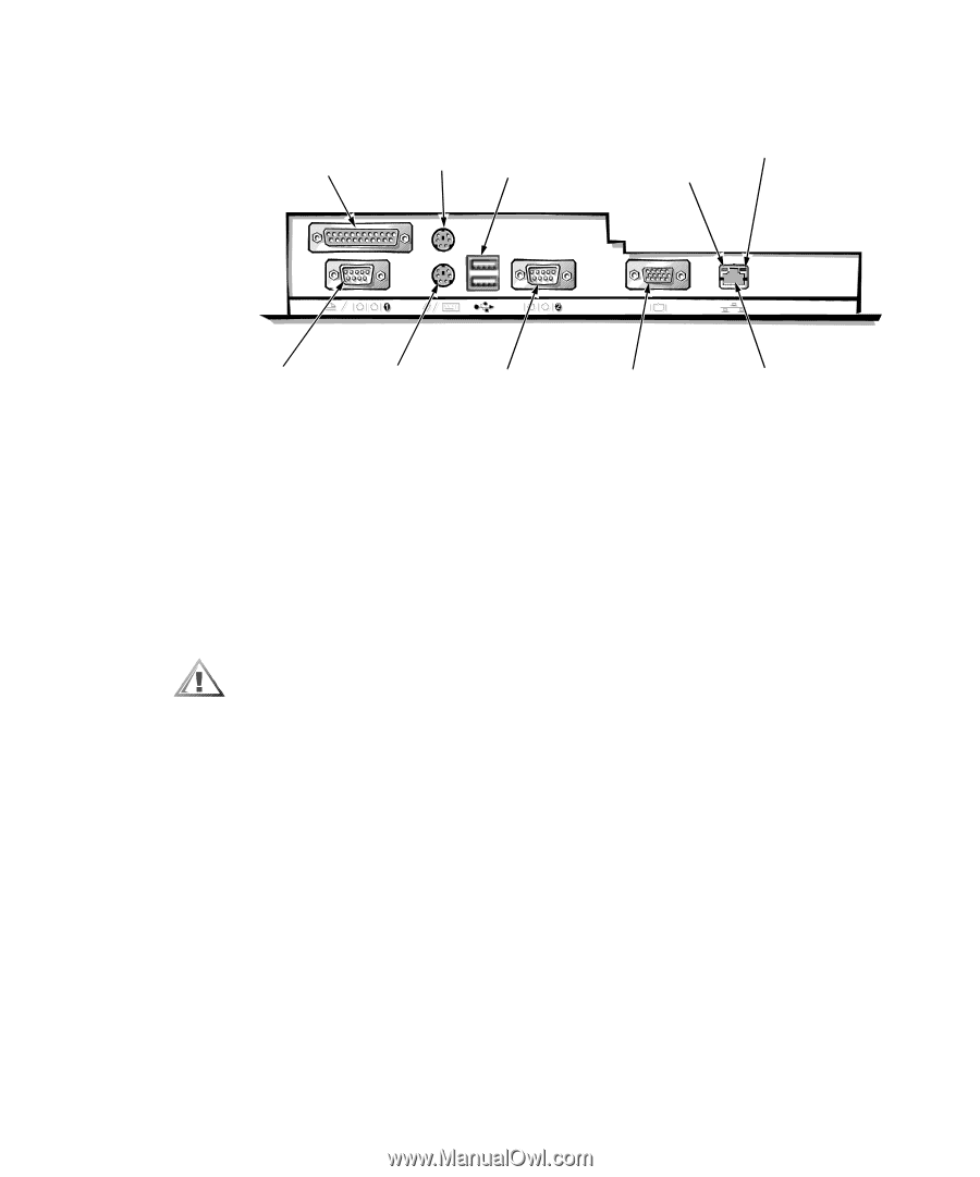
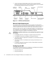
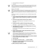
A green link integrity indicator lights up when there is a good connection between the network and the NIC. When the green indicator is off, the computer is not detecting a physical connection to the network. parallel port connector mouse connector USB link integrity connectors (2) indicator activity indicator serial port 1 connector keyboard connector serial port 2 connector video connector optional integrated NIC connector Your computer's NIC connector (an RJ45 connector located on the back panel) is designed for attaching an unshielded twisted pair (UTP) Ethernet cable. Press one end of the UTP cable into the NIC connector until the cable snaps securely into place. Connect the other end of the cable to an RJ45 jack wall plate or to an RJ45 port on a UTP concentrator or hub, depending on your network configuration. Observe the following cabling restrictions for 10BASE-T and 100BASE-TX networks. For 10BASE-T networks, use Category 3 or greater wiring and connectors. For 100BASE-TX networks, use Category 5 wiring and connectors. The maximum cable run length (from a workstation to a concentrator) is 328 feet (ft) (100 meters [m]). The maximum number of workstations (not counting concentrators) on a network is 1024. For 10BASE-T networks, the maximum number of daisy-chained concentrators on one network segment is four. This subsection provides instructions for configuring or reconfiguring the computer's integrated NIC under the following operating systems: Microsoft Windows NT Microsoft Windows 95 4-2 Dell OptiPlex G1 Mini Tower Managed PC Reference and Installation Guide
-
 1
1 -
2
-
3
-
4
-
5
-
6
-
7
-
8
-
9
-
10
-
11
-
12
-
13
-
14
-
15
-
16
-
17
-
18
-
19
-
20
-
21
-
22
-
23
-
24
-
25
-
26
-
27
-
28
-
29
-
30
-
31
-
32
-
33
-
34
-
35
-
36
-
37
-
38
-
39
-
40
-
41
-
42
-
43
-
44
-
45
-
46
-
47
-
48
-
49
-
50
-
51
-
52
-
53
-
54
-
55
-
56
-
57
-
58
-
59
-
60
-
61
-
62
-
63
-
64
-
65
-
66
-
67
-
68
-
 69
69 -
 70
70 -
 71
71 -
 72
72 -
 73
73 -
 74
74 -
 75
75 -
 76
76 -
 77
77 -
 78
78 -
 79
79 -
80
-
81
-
82
-
83
-
84
-
85
-
86
-
87
-
88
-
89
-
90
-
91
-
92
-
93
-
94
-
95
-
96
-
97
-
98
-
99
-
100
-
101
-
102
-
103
-
104
-
105
-
106
-
107
-
108
-
109
-
110
-
111
-
112
-
113
-
114
-
115
-
116
-
117
-
118
-
119
-
120
-
121
-
122
-
123
-
124
-
125
-
126
-
127
-
128
-
129
-
130
-
131
-
132
-
133
-
134
-
135
-
136
-
137
-
138
-
139
-
140
-
141
-
142
-
143
-
144
-
145
-
146
-
147
-
148
-
149
-
150
-
151
-
152
-
153
-
154
-
155
-
156
-
157
-
158
-
159
-
160
-
161
-
162
-
163
-
164
 |
 |