Dell OptiPlex GX1p Dell OptiPlex GX1 and GX1p Midsize Managed PC Systems Refe - Page 98
front of computer
 |
View all Dell OptiPlex GX1p manuals
Add to My Manuals
Save this manual to your list of manuals |
Page 98 highlights
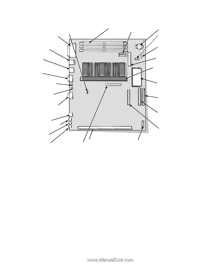
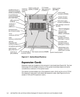
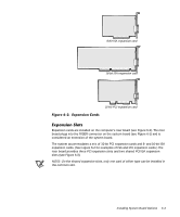
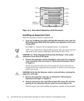
parallel/serial port 1 connectors (stacked) (PARALLEL/SERIAL1) telephony connector (TAPI) DIMM sockets (3) (DIMM_A-DIMM_C) mouse/keyboard connectors (stacked) (MOUSE/KYBD) 3.3-V power input connector (POWER_2) USB connectors (USB) (2) serial port 2 connector (SERIAL2) battery socket (BATTERY) control panel connector (PANEL) chassis intrusion switch connector main power input connector (POWER_1) SEC cartridge connector (SLOT1) microprocessor fan connector (FAN) CD-in connector (CD-IN) video connector MONITOR) front of computer video-memor y upgrade socket (VIDEO_UPGRADE) primary EIDE interface connector (IDE1) (pin-1 corner) optional integrated NIC connector (ENET) microphone jack (MIC) audio line-out jack (LINE-OUT) audio line-in jack (LINE-IN) ATI multimedia connector (AMC) riser board connector (RISER) secondary EIDE interface connector (IDE2) (pin-2 corner) diskette/tape drive interface connector (DSKT) (pin-1 corner) system board jumpers Expansion cards are installed on the computer's riser board (see Figure 6-3). The riser board plugs into the RISER connector on the system board (see Figure 6-1) and is considered an extension of the system board. The system accommodates up to five expansion cards, which can be a mix of 32-bit PCI expansion cards and 8- and 16-bit ISA expansion cards. (See Figure 6-2 for examples of ISA and PCI expansion cards.) 6-2 Dell OptiPlex GX1 and GX1p Midsize Managed PC Systems Reference and Installation Guide
-
 1
1 -
2
-
3
-
4
-
5
-
6
-
7
-
8
-
9
-
10
-
11
-
12
-
13
-
14
-
15
-
16
-
17
-
18
-
19
-
20
-
21
-
22
-
23
-
24
-
25
-
26
-
27
-
28
-
29
-
30
-
31
-
32
-
33
-
34
-
35
-
36
-
37
-
38
-
39
-
40
-
41
-
42
-
43
-
44
-
45
-
46
-
47
-
48
-
49
-
50
-
51
-
52
-
53
-
54
-
55
-
56
-
57
-
58
-
59
-
60
-
61
-
62
-
63
-
64
-
65
-
66
-
67
-
68
-
69
-
70
-
71
-
72
-
73
-
74
-
75
-
76
-
77
-
78
-
79
-
80
-
81
-
82
-
83
-
84
-
85
-
86
-
87
-
88
-
89
-
90
-
91
-
92
-
 93
93 -
 94
94 -
 95
95 -
 96
96 -
 97
97 -
 98
98 -
 99
99 -
 100
100 -
 101
101 -
 102
102 -
 103
103 -
104
-
105
-
106
-
107
-
108
-
109
-
110
-
111
-
112
-
113
-
114
-
115
-
116
-
117
-
118
-
119
-
120
-
121
-
122
-
123
-
124
-
125
-
126
-
127
-
128
-
129
-
130
-
131
-
132
-
133
-
134
-
135
-
136
-
137
-
138
-
139
-
140
-
141
-
142
-
143
-
144
-
145
-
146
-
147
-
148
-
149
-
150
-
151
-
152
-
153
-
154
-
155
-
156
-
157
-
158
-
159
-
160
-
161
-
162
-
163
-
164
-
165
-
166
-
167
-
168
-
169
-
170
-
171
-
172
-
173
-
174
 |
 |