Dell Optiplex Dell OptiPlex GX1/GX1p Managed PC and OptiPlex NX1 Net PC Syste - Page 43
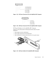
connectors must be connected to their corresponding power input connectors
 |
UPC - 718122898176
View all Dell Optiplex manuals
Add to My Manuals
Save this manual to your list of manuals |
Page 43 highlights
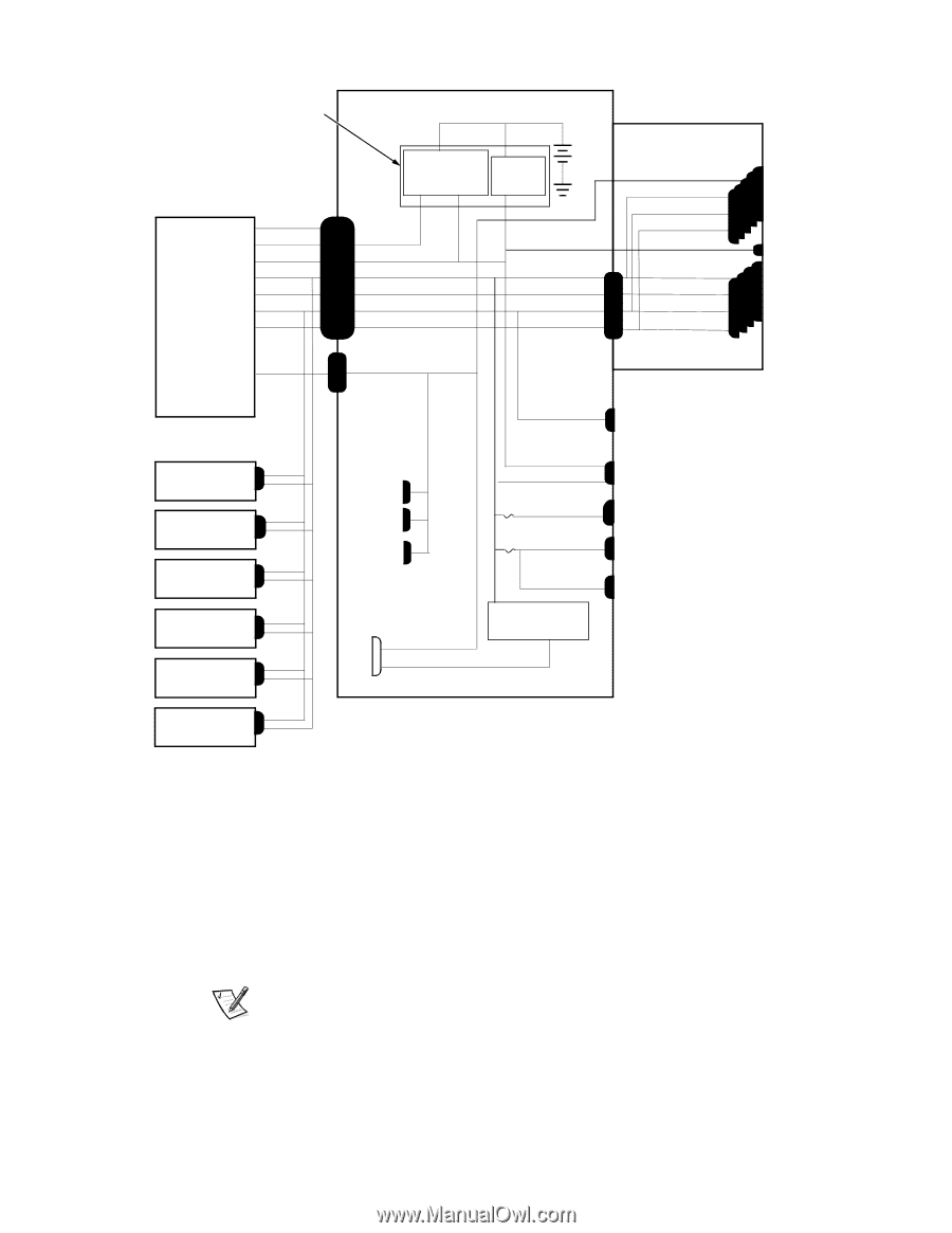
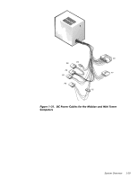
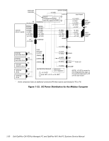
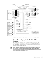
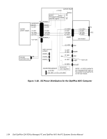
keyboard controller P1 PWRGOOD system board +3 VDC battery power management RTC/ and NIC logic NVRAM POWER1 system power supply PSON# +5 VFP +5 VDC -5 VDC +12 VDC -12 VDC P7 +3.3 VDC PSON# +5 VFP +5 VDC -5 VDC +12 VDC -12 VDC POWER2 +5 VDC -5 VDC +12 VDC -12 VDC RISER riser board +3.3 VDC +5 VDC +12 VDC -12 VDC +5 VFP +5 VDC -5 VDC +12 VDC -12 VDC PCI1 through PCI5 P1 ISA1 through ISA4 internal P2 hard-disk drive internal P3 hard-disk drive P4 3.5-inch diskette drive P5 optional drive P6 optional drive P9 optional drive main memory sockets DIMM_A DIMM_B DIMM_C +12 VDC FAN +5 VFP +5 VDC +5 VDC +5 VDC PANEL USB KYBD +5 VDC processor MICROPROCESSOR core regulator +3.3 VDC core VCC +2.1 to +3.5 VDC MOUSE NOTE: +5 VFP is routed to the integrated NIC logic on the system board and to P1 on the riser board. The OptiPlex NX1 computers have an 80-W computer power supply. The power supply can operate from an AC power source of 115 VAC at 60 Hz or 230 VAC at 50 Hz. The system power supply provides the DC operating voltages and currents listed in Table 1-5. NOTE: The power supply produces DC voltages only under its loaded condition. Therefore, when you measure these voltages, the DC power input connectors must be connected to their corresponding power input connectors on the system board and hard-disk drive. System Overview 1-31
-
 1
1 -
2
-
3
-
4
-
5
-
6
-
7
-
8
-
9
-
10
-
11
-
12
-
13
-
14
-
15
-
16
-
17
-
18
-
19
-
20
-
21
-
22
-
23
-
24
-
25
-
26
-
27
-
28
-
29
-
30
-
31
-
32
-
33
-
34
-
35
-
36
-
37
-
 38
38 -
 39
39 -
 40
40 -
 41
41 -
 42
42 -
 43
43 -
 44
44 -
 45
45 -
 46
46 -
 47
47 -
 48
48 -
49
-
50
-
51
-
52
-
53
-
54
-
55
-
56
-
57
-
58
-
59
-
60
-
61
-
62
-
63
-
64
-
65
-
66
-
67
-
68
-
69
-
70
-
71
-
72
-
73
-
74
-
75
-
76
-
77
-
78
-
79
-
80
-
81
-
82
-
83
-
84
-
85
-
86
-
87
-
88
-
89
-
90
-
91
-
92
-
93
-
94
-
95
-
96
-
97
-
98
-
99
-
100
-
101
-
102
-
103
-
104
-
105
-
106
-
107
-
108
-
109
-
110
-
111
-
112
-
113
-
114
-
115
-
116
-
117
-
118
-
119
-
120
-
121
-
122
-
123
-
124
-
125
-
126
-
127
-
128
-
129
-
130
-
131
-
132
-
133
-
134
-
135
-
136
-
137
-
138
-
139
-
140
-
141
-
142
-
143
-
144
-
145
-
146
-
147
-
148
-
149
-
150
-
151
-
152
-
153
-
154
-
155
-
156
-
157
-
158
-
159
-
160
-
161
-
162
-
163
-
164
-
165
-
166
-
167
-
168
-
169
-
170
-
171
-
172
-
173
-
174
-
175
-
176
-
177
-
178
 |
 |