Dell PowerApp 220 Microprocessor Upgrade Installation Guide - Page 6
heat sink on the microprocessor., If heat sink thermal grease is provided
 |
View all Dell PowerApp 220 manuals
Add to My Manuals
Save this manual to your list of manuals |
Page 6 highlights
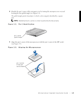
www.dell.com | support.dell.com CAUTION: Positioning the microprocessor incorrectly can permanently damage the microprocessor and the system when you turn on the system. 10 Install the microprocessor in the socket. a If the release lever on the ZIF socket is not in the upright position, move it to that position now. NOTICE: When placing the microprocessor in the ZIF socket, be sure that all of the pins on the microprocessor go into the corresponding holes. Be careful not to bend the pins. b With the pin-1 corners of the microprocessor and socket aligned, set the microprocessor lightly in the socket and make sure that all pins are matched with the correct holes in the socket. Because the system uses a ZIF microprocessor socket, there is no need to use force (which could bend the pins if the chip is misaligned). When the microprocessor is positioned correctly, it should drop down into the socket with minimal pressure. c When the microprocessor is fully seated in the socket, rotate the socket release lever back down until it snaps into place, locking the microprocessor in the socket. 11 Install the heat sink. • If the heat sink provided has a foil thermal interface material strip on the bottom of the heat sink, place the heat sink on the microprocessor. • If the heat sink provided has a thermal grease tab, remove the tab and place the heat sink on the microprocessor. • If heat sink thermal grease is provided, clean the heat sink and apply the thermal grease before placing the heat sink on the microprocessor. Refer to your system information label on the system cover for the correct heat sink orientation. NOTICE: To avoid possible damage to the microprocessor, you must align the heat sink so that the triangular mark on the heat sink points toward the triangular mark on the system board. 12 To replace the retention clip, orient the clip as shown on the system information label. 13 Hook the end of the clip without the release tab over the tab on the edge of the socket. 14 Press down on the release tab until the hole on the clip latches onto the ZIF socket tab. 15 If you are adding a secondary microprocessor, examine the VRM to ensure that it is the correct VRM for your system. 16 Insert the VRM in the appropriate secondary VRM socket, making sure that the latches at each end of the socket engage (see Figure 1-4). 1-4 Microprocessor Upgrade Installation Guide
-
 1
1 -
 2
2 -
 3
3 -
 4
4 -
 5
5 -
 6
6 -
 7
7 -
 8
8
 |
 |
