Dell PowerConnect W-AP124 Dell PowerConnect W-AP120 Series AP Installation Gui - Page 6
Connecting Required Cables
 |
View all Dell PowerConnect W-AP124 manuals
Add to My Manuals
Save this manual to your list of manuals |
Page 6 highlights
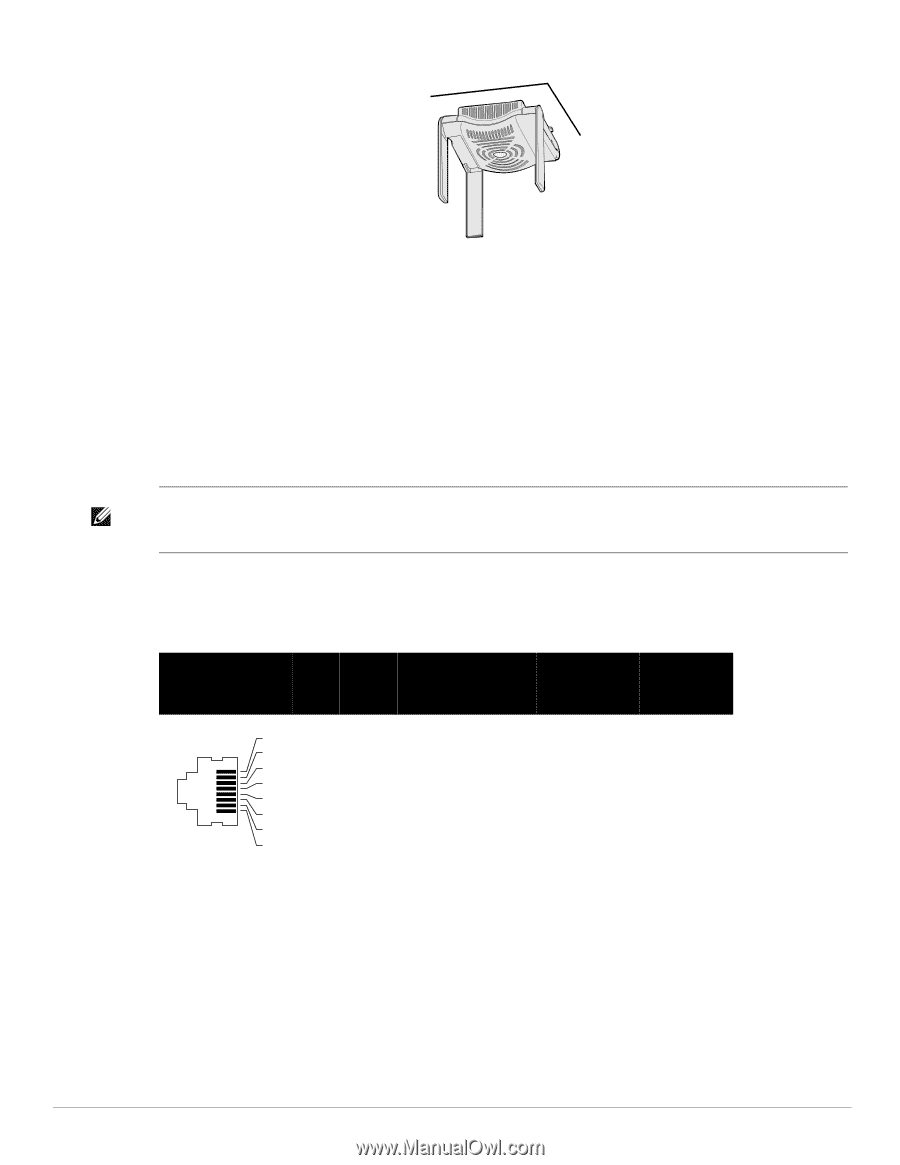
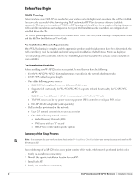
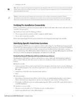
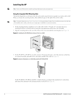
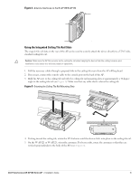
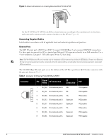
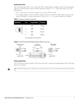
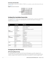
Figure 6 Antenna Orientation on a Ceiling-Mounted W-AP121/W-AP125 On the W-AP120 or W-AP124, install the external antennas according to the manufacturer's instructions, and connect the antennas to the antenna interfaces on the AP (see Figure 4). Connecting Required Cables Install cables in accordance with all applicable local and national regulations and practices. Ethernet Ports The RJ45 Ethernet ports (ENET0 and ENET1) support 100/1000Base-T auto-sensing MDI/MDX connections. Use these ports to connect the AP to a twisted pair Ethernet LAN segment or directly to an Dell controller. Use a 4- or 8-conductor, Category 5 UTP cable up to 100 m (325 feet) long. Note: Dell W-AP120 series APs are intended only for installation in Environment A as defined in IEEE 802.3.af, Power over Ethernet. All interconnected equipment must be contained within the same building, including the interconnected equipment's associated LAN connections. The 100/1000 Mbps Ethernet ports are on the bottom of the AP. These ports have RJ-45 female connectors with the pin-outs shown in Table 1. Table 1 Connector for Ethernet Ports ENET0 and ENET1 Connector Pin Signal Name GE Connection FE Connection PoE 11 2 32 4 53 6 74 8 5 6 7 8 BI_DA+ Bi-directional pair A+ RX+ BI_DA- Bi-directional pair A- RX- BI_DB+ Bi-directional pair B+ TX+ BI_DC+ Bi-directional pair C+ Spare pair BI_DC- Bi-directional pair C- Spare pair BI_DB- Bi-directional pair B- TX- BI_DD+ Bi-directional pair D+ Spare pair BI_DB- Bi-directional pair D- Spare pair POE negative POE negative POE positive POE positive POE positive POE positive POE negative POE negative 6 Dell PowerConnect W-AP120 Series AP | Installation Guide
-
 1
1 -
 2
2 -
 3
3 -
 4
4 -
 5
5 -
 6
6 -
 7
7 -
 8
8 -
 9
9 -
 10
10 -
 11
11 -
 12
12 -
13
-
14
-
15
-
16
-
17
-
18
-
19
-
20
-
21
-
22
-
23
-
24
-
25
-
26
-
27
-
28
-
29
-
30
-
31
-
32
-
33
-
34
-
35
-
36
-
37
-
38
-
39
-
40
-
41
-
42
-
43
-
44
-
45
-
46
-
47
-
48
-
49
-
50
-
51
-
52
-
53
-
54
-
55
-
56
-
57
-
58
-
59
-
60
-
61
-
62
-
63
-
64
-
65
-
66
-
67
-
68
-
69
-
70
-
71
-
72
-
73
-
74
-
75
-
76
-
77
-
78
-
79
-
80
-
81
-
82
-
83
-
84
-
85
-
86
-
87
-
88
-
89
-
90
-
91
-
92
-
93
-
94
-
95
-
96
-
97
-
98
-
99
-
100
-
101
-
102
-
103
-
104
-
105
-
106
-
107
-
108
-
109
-
110
-
111
-
112
-
113
-
114
-
115
-
116
-
117
-
118
-
119
-
120
-
121
-
122
-
123
-
124
-
125
-
126
-
127
-
128
-
129
-
130
-
131
-
132
-
133
-
134
-
135
-
136
-
137
-
138
-
139
-
140
-
141
-
142
-
143
-
144
-
145
-
146
-
147
-
148
-
149
-
150
-
151
-
152
-
153
-
154
-
155
-
156
-
157
-
158
 |
 |