Dell PowerConnect W-Series FIPS Dell PowerConnect W-AP92/93, W-AP105, W-AP175 - Page 27
Configuring Control Plane Security CPSec protected AP FIPS mode
 |
View all Dell PowerConnect W-Series FIPS manuals
Add to My Manuals
Save this manual to your list of manuals |
Page 27 highlights
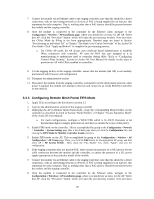
6. If the staging controller does not provide PoE, either ensure the presence of a PoE injector for the LAN connection between the module and the controller, or ensure the presence of a DC power supply appropriate to the particular model of the module. 7. Connect the module via an Ethernet cable to the staging controller; note that this should be a direct connection, with no intervening network or devices; if PoE is being supplied by an injector, this represents the only exception. That is, nothing other than a PoE injector should be present between the module and the staging controller. 8. Once the module is connected to the controller by the Ethernet cable, navigate to the Configuration > Wireless > AP Installation page, where you should see an entry for the AP. Select that AP, click the "Provision" button, which will open the provisioning window. Now provision the AP as Remote AP by filling in the form appropriately. Detailed steps are listed in Section "Provisioning an Individual AP" of Chapter "The Basic User-Centric Networks" of the Aruba OS User Guide. Click "Apply and Reboot" to complete the provisioning process. a. During the provisioning process as Remote AP if Pre-shared key is selected to be the Remote IP Authentication Method, the IKE pre-shared key (which is at least 8 characters in length) is input to the module during provisioning. Generation of this key is outside the scope of this policy. In the initial provisioning of an AP, this key will be entered in plaintext; subsequently, during provisioning, it will be entered encrypted over the secure IPSec session. If certificate based authentication is chosen, AP's RSA key pair is used to authenticate AP to controller during IPSec. AP's RSA private key is contained in the AP's non volatile memory and is generated at manufacturing time in factory. 9. Via the logging facility of the staging controller, ensure that the module (the AP) is successfully provisioned with firmware and configuration 10. Terminate the administrative session 11. Disconnect the module from the staging controller, and install it on the deployment network; when power is applied, the module will attempt to discover and connect to an Aruba Mobility Controller on the network. 3.3.2 Configuring Control Plane Security (CPSec) protected AP FIPS mode 1. Apply TELs according to the directions in section 3.2 2. Log into the administrative console of the staging controller 3. Deploying the AP in CPSec AP mode, configure the staging controller with CPSec under Configuration > Controller > Control Plane Security tab. AP will authenticate to the controller using certificate based authentication to establish IPSec. AP is configured with RSA key pair at manufacturing. AP's certificate is signed by Aruba Certification Authority (trusted by all Aruba controllers) and the AP's RSA private key is stored in non-volatile memory. Refer to "Configuring Control Plane Security" Section in ArubaOS User Manual for details on the steps. 4. Enable FIPS mode on the controller. This is accomplished by going to the Configuration > Network > Controller > System Settings page (this is the default page when you click the Configuration tab), and clicking the FIPS Mode for Mobility Controller Enable checkbox. 5. Enable FIPS mode on the AP. This accomplished by going to the Configuration > Wireless > AP Configuration > AP Group page. There, you click the Edit button for the appropriate AP group, and then select AP > AP System Profile. Then, check the "Fips Enable" box, check "Apply", and save the configuration. 6. If the staging controller does not provide PoE, either ensure the presence of a PoE injector for the LAN connection between the module and the controller, or ensure the presence of a DC power supply appropriate to the particular model of the module 27
-
 1
1 -
2
-
3
-
4
-
5
-
6
-
7
-
8
-
9
-
10
-
11
-
12
-
13
-
14
-
15
-
16
-
17
-
18
-
19
-
20
-
21
-
 22
22 -
 23
23 -
 24
24 -
 25
25 -
 26
26 -
 27
27 -
 28
28 -
 29
29 -
 30
30 -
 31
31 -
 32
32 -
33
-
34
-
35
-
36
-
37
-
38
-
39
-
40
-
41
-
42
-
43
-
44
-
45
 |
 |
