Dell PowerEdge 2450 Installation and Troubleshooting Guide (.pdf) - Page 4
Recommended Tools, Marking the Rack, DELL CONFIDENTIAL - Preliminary
 |
View all Dell PowerEdge 2450 manuals
Add to My Manuals
Save this manual to your list of manuals |
Page 4 highlights
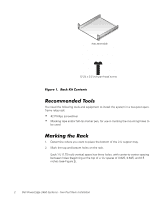
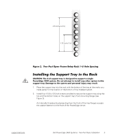
(Rev. 11/3/98) FILE LOCATION: C:\Dell\docs\2450\2post\81HFFts0.fm tray assembly 12-24 x 0.5 inch pan-head screw Figure 1. Rack Kit Contents Recommended Tools You need the following tools and equipment to install the system in a two-post openframe relay rack: • #2 Phillips screwdriver • Masking tape and/or felt-tip marker pen, for use in marking the mounting holes to be used Marking the Rack 1. Determine where you want to place the bottom of the 2-U support tray. 2. Mark the top and bottom holes on the rack. Each 1-U (1.75-inch) vertical space has three holes, with center-to-center spacing between holes (beginning at the top of a 1-U space) of 0.625, 0.625, and 0.5 inches (see Figure 2). DELL CONFIDENTIAL - Preliminary 9/27/01 2 Dell PowerEdge 2450 Systems - Two-Post Rack Installation
-
 1
1 -
 2
2 -
 3
3 -
 4
4 -
 5
5 -
 6
6 -
 7
7 -
 8
8
 |
 |
