Dell PowerEdge 6400 Expansion-Card Cooling Fan Assembly Installation Info - Page 6
Installation and Troubleshooting Guide, card bracket.
 |
View all Dell PowerEdge 6400 manuals
Add to My Manuals
Save this manual to your list of manuals |
Page 6 highlights
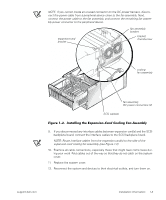
4. Press the system-board tray latch at the lower-back corner of the tray (see Figure 1-1). tray latch system board tray 5. Pull the tray open to the first slide position. 6. If any interface cables are connected between expansion card(s) and the small computer system interface (SCSI) backplane board, disconnect the interface cables from the SCSI backplane board. 7. Install the expansion-card cooling fan assembly (see Figure 1-2): a. Insert the tabs at the bottom of the fan assembly into expansion-card bracket at slots PCI2 and PCI6. To identify slots PCI2 and PCI6, see "Expansion Cards" in your system's Installation and Troubleshooting Guide. b. Press the top of the fan assembly and slide it under the top of the expansioncard bracket. c. Secure the fan assembly bracket to the expansion-card bracket, and tighten the fan assembly bracket thumbscrew. NOTE: If you cannot install the fan assembly on the expansion-card bracket, replace the expansion-card guides with those included in the fan assembly upgrade kit. 8. Locate an available connector on the DC power harness, and connect it to one of the two fan assembly DC power connectors. 1-2 Installation Information
-
 1
1 -
 2
2 -
 3
3 -
 4
4 -
 5
5 -
 6
6 -
 7
7 -
 8
8 -
 9
9 -
 10
10 -
 11
11 -
 12
12 -
13
-
14
-
15
-
16
-
17
-
18
-
19
-
20
-
21
-
22
-
23
-
24
-
25
-
26
-
27
-
28
-
29
-
30
-
31
-
32
 |
 |
