Dell PowerEdge 6400 Expansion-Card Cooling Fan Assembly Installation Info - Page 7
bly power connector to the peripheral device. - fan
 |
View all Dell PowerEdge 6400 manuals
Add to My Manuals
Save this manual to your list of manuals |
Page 7 highlights
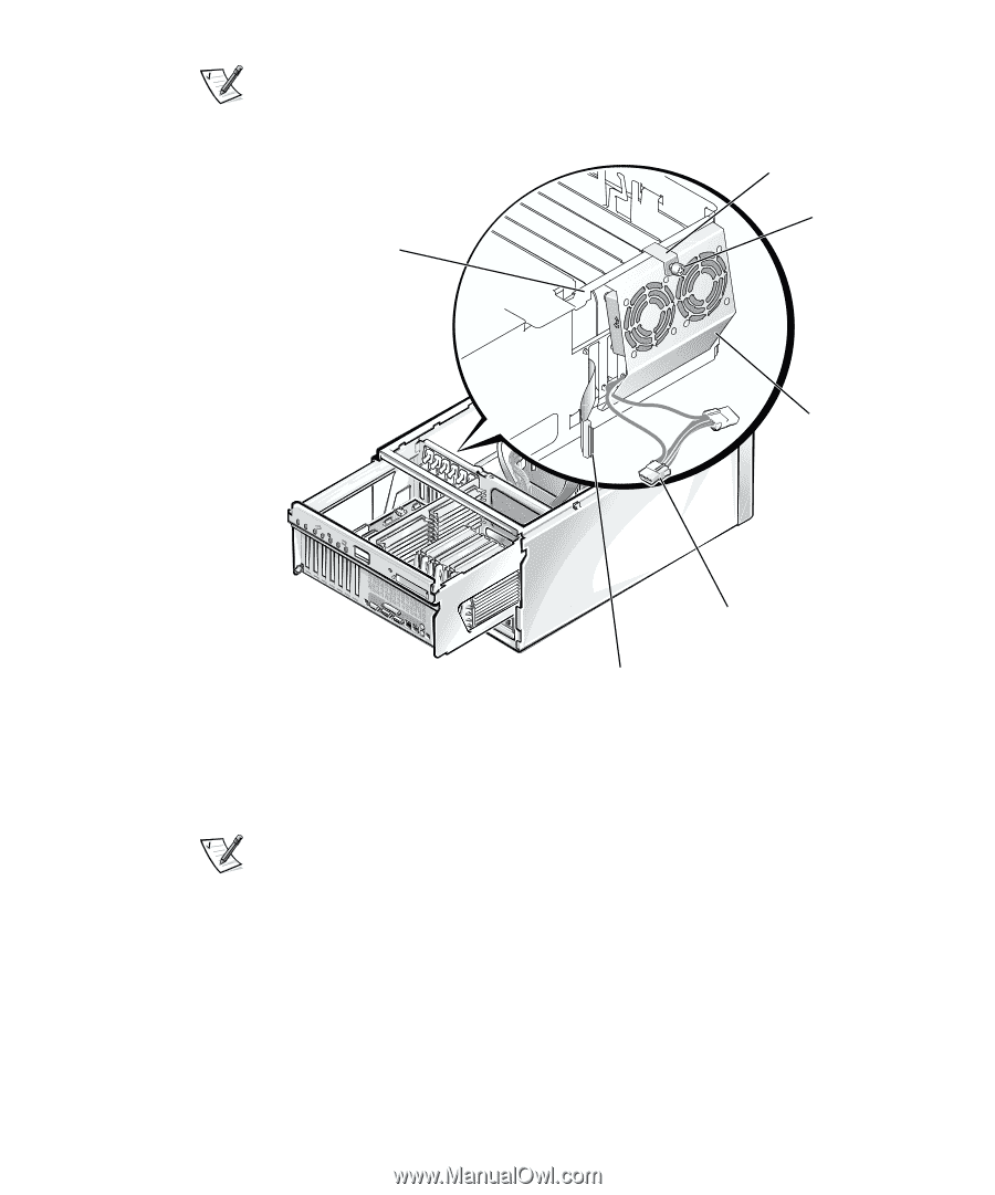
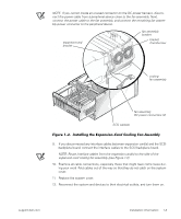
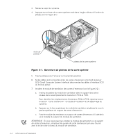
NOTE: If you cannot locate an unused connector on the DC power harness, disconnect the power cable from a peripheral device close to the fan assembly. Next, connect the power cable to the fan assembly, and connect the remaining fan assembly power connector to the peripheral device. expansion-card bracket fan assembly bracket bracket thumbscrew cooling fan assembly fan assembly DC power connectors (2) SCSI cable(s) 9. If you disconnected any interface cables between expansion card(s) and the SCSI backplane board, connect the interface cables to the SCSI backplane board. NOTE: Route interface cables from the expansion card(s) to the side of the expansion-card cooling fan assembly (see Figure 1-2). 10. Examine all cable connections, especially those that might have come loose during your work. Fold cables out of the way so that they do not catch on the system cover. 11. Replace the system cover. 12. Reconnect the system and devices to their electrical outlets, and turn them on. support.dell.com Installation Information 1-3
-
 1
1 -
 2
2 -
 3
3 -
 4
4 -
 5
5 -
 6
6 -
 7
7 -
 8
8 -
 9
9 -
 10
10 -
 11
11 -
 12
12 -
13
-
14
-
15
-
16
-
17
-
18
-
19
-
20
-
21
-
22
-
23
-
24
-
25
-
26
-
27
-
28
-
29
-
30
-
31
-
32
 |
 |