Dell PowerEdge M915 Technical Guide - Page 27
Overview, DIMMs Supported, DIMM Slots, DIMM Population Guidelines, Memory Speed
 |
View all Dell PowerEdge M915 manuals
Add to My Manuals
Save this manual to your list of manuals |
Page 27 highlights
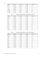
Dell 7 Memory 7.1 Overview The Dell™ PowerEdge™ M915 uses DDR3 memory, providing a high performance, high-speed memory interface capable of low latency response and high throughput. The platform supports registered ECC DDR3L DIMMs (LV RDIMM). The M915 memory system supports up to 32 DIMMs. 7.2 DIMMs Supported The M915 memory interface uses 1GB, 2GB, 4GB, 8GB, 16GB and 32GB DIMMs. UDIMMs are not supported. 7.3 DIMM Slots The M915 has 32 DIMM slots, organized in four channels per processor. The first DIMM slot in each channel is color-coded with white ejection tabs for ease of installation. The DIMM sockets are placed 400 mils (11mm) apart, center-to-center in order to provide enough space for sufficient airflow to cool stacked DIMMs. 7.4 DIMM Population Guidelines The DDR3 memory interface consists of 4 memory channels per processor socket. Each channel supports up to two LV RDIMMs for single-,dual-, and quad-rank DIMMs. Each channel is capable of supporting up to two DDR3 memory modules. For optimal performance, the following memory configuration rules should be observed: Memory modules must be installed in pairs, beginning with the first two sockets in each set of memory modules. These sockets are marked by white retention levers. The memory configuration for each processor must be identical. Memory modules must be identical in size, speed, and technology in corresponding slots. If quad-rank memory modules are mixed with single- or dual-rank modules, the quad-rank modules must be installed in the sockets with the white release levers. If pairs of memory modules of different sizes are installed, the larger capacity memory modules must be in the lower numbered slots. DIMMs must be installed in each channel starting with the DIMM farthest from the processor (DIMM 1). Population order is identified by the silkscreen designator and the System Information Label (SIL) located on the chassis cover. System performance can be affected if memory configurations do not conform to the preceding installation guidelines. The system may issue an error message during start-up that the configuration is non-optimal. 7.5 Memory Speed The memory frequency is determined by a variety of inputs: Each processor has 4 DDR3 channels capable of supporting speeds up to 1600MT/s. Single-rank, dual-rank, and mixed single- and dual-rank DIMM types can support speeds up to 1600MT/s. PowerEdge M915 Technical Guide 27
-
 1
1 -
2
-
3
-
4
-
5
-
6
-
7
-
8
-
9
-
10
-
11
-
12
-
13
-
14
-
15
-
16
-
17
-
18
-
19
-
20
-
21
-
 22
22 -
 23
23 -
 24
24 -
 25
25 -
 26
26 -
 27
27 -
 28
28 -
 29
29 -
 30
30 -
 31
31 -
 32
32 -
33
-
34
-
35
-
36
-
37
-
38
-
39
-
40
-
41
-
42
-
43
-
44
-
45
-
46
-
47
-
48
-
49
-
50
-
51
-
52
-
53
-
54
-
55
 |
 |
