Dell PowerEdge MX840c EMC PowerEdge MX7000 Enclosure Installation and Service
Dell PowerEdge MX840c Manual
 |
View all Dell PowerEdge MX840c manuals
Add to My Manuals
Save this manual to your list of manuals |
Dell PowerEdge MX840c manual content summary:
- Dell PowerEdge MX840c | EMC PowerEdge MX7000 Enclosure Installation and Service - Page 1
Dell EMC PowerEdge MX7000 Enclosure Installation and Service Manual Regulatory Model: E44S Series Regulatory Type: E44S001 May 2020 Rev. A06 - Dell PowerEdge MX840c | EMC PowerEdge MX7000 Enclosure Installation and Service - Page 2
data and tells you how to avoid the problem. WARNING: A WARNING indicates a potential for property damage, personal injury, or death. © 2018 2020 Dell Inc. or its subsidiaries. All rights reserved. Dell, EMC, and other trademarks are trademarks of Dell Inc. or its subsidiaries. Other trademarks may - Dell PowerEdge MX840c | EMC PowerEdge MX7000 Enclosure Installation and Service - Page 3
or storage sled from the enclosure 29 Installing a compute or storage sled into the enclosure 31 Cooling fan modules...33 Removing a front fan module...33 Installing a front fan module...33 Removing a rear fan module...34 Installing a rear fan module...35 Power supply units ...35 Contents 3 - Dell PowerEdge MX840c | EMC PowerEdge MX7000 Enclosure Installation and Service - Page 4
Removing a power supply unit...35 Installing a power supply unit...36 Acoustic baffle...37 Removing the air baffle...37 Installing the air baffle...38 Fabrics and modules...39 Removing a blank from Fabric A or B slot...39 Installing a blank in Fabric A or B slot...39 Removing a module from Fabric A - Dell PowerEdge MX840c | EMC PowerEdge MX7000 Enclosure Installation and Service - Page 5
Contacting Dell EMC...60 Documentation feedback...61 Accessing system information by using QRL...61 Quick Resource Locator for PowerEdge MX7000 enclosure 61 Receiving automated support with SupportAssist ...61 8 Documentation resources...62 Contents 5 - Dell PowerEdge MX840c | EMC PowerEdge MX7000 Enclosure Installation and Service - Page 6
1 About this document This document provides an overview about the PowerEdge MX7000, information about installing and replacing components, technical specifications, and guidelines to follow while installing components. 6 About this document - Dell PowerEdge MX840c | EMC PowerEdge MX7000 Enclosure Installation and Service - Page 7
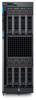
2 Next Generation Modular overview Figure 1. Next Generation Modular - Front view • Compute sleds - MX740c, and MX840c • Storage sled - MX5016s Next Generation Modular overview 7 - Dell PowerEdge MX840c | EMC PowerEdge MX7000 Enclosure Installation and Service - Page 8
Generation Modular - Back view The Dell EMC PowerEdge MX7000 enclosure supports the following sleds and I/O modules: • I/O modules - ○ Dell EMC Networking MX7116n Fabric Expander Module ○ Dell EMC Networking MX9116n Fabric Switching Engine ○ Dell EMC Networking MX5108n Ethernet Switch ○ Dell EMC - Dell PowerEdge MX840c | EMC PowerEdge MX7000 Enclosure Installation and Service - Page 9
chassis power, cooling, and hosts the OpenManage EnterpriseModular (OME-M) console. Two external 1G-BaseT Ethernet ports are provided to enable management connectivity and to connect more PowerEdge MX7000 chassis into a single logical chassis. The PowerEdge MX7000 chassis supports two PowerEdge - Dell PowerEdge MX840c | EMC PowerEdge MX7000 Enclosure Installation and Service - Page 10
pass-through module does not support 1G mezzanine cards in the sleds. • Dell EMC PowerEdge MX 25 Gb Ethernet Pass- , and lower power consumption. The 25GbE SFP28 physical interface specification also supports various form factors dell.com/poweredgemanuals. 10 Next Generation Modular overview - Dell PowerEdge MX840c | EMC PowerEdge MX7000 Enclosure Installation and Service - Page 11
overview The Dell EMC PowerEdge MX7000 is the next-generation M1000e follow-on chassis and a revolutionary architecture set to be the future foundation of modular architecture. The PowerEdge MX7000 enclosure is a 7U chassis that supports: • Up to eight standard height, single-width sleds, or - Dell PowerEdge MX840c | EMC PowerEdge MX7000 Enclosure Installation and Service - Page 12
Front view of the enclosure Figure 3. Front view of the enclosure 1. Left control panel 3. Sled blank 5. Double-width compute sled 7. Right control panel 9. Power supply unit (6) Control panel Left control panel 2. Single-width compute sled 4. Front fan (4) 6. Single-width storage sled 8. - Dell PowerEdge MX840c | EMC PowerEdge MX7000 Enclosure Installation and Service - Page 13
panel to identify the chassis, or choose specific sleds to indicator on LCD identify. panel 4 Settings This option button provides access to the inventory and configuration data of the MX7000 enclosure. It includes the Network Settings, System Information, (Model, Asset Tag, Service Tag), and - Dell PowerEdge MX840c | EMC PowerEdge MX7000 Enclosure Installation and Service - Page 14
of purchase, the QuickSync module will not be available on the enclosure. 6 System alerts System ID Indicator status Description indicator Solid green The chassis has no degraded or critical alerts. Solid amber The chassis has critical or degraded health alerts. NOTE: This option button - Dell PowerEdge MX840c | EMC PowerEdge MX7000 Enclosure Installation and Service - Page 15
Figure 7. PSU indicators 1. PSU health indicator 2. AC supply status indicator 3. DC output status indicator Table 3. PSU indicator Indicator state AC source available ON AC source unavailable or OFF power cable unplugged Table 5. DC indicator codes DC indicator Indicator state DC output - Dell PowerEdge MX840c | EMC PowerEdge MX7000 Enclosure Installation and Service - Page 16
Solid green Blinks amber 2 seconds and 1 second OFF NOTE: When the chassis is powered off with the AC connection that is powered on, only the rear fans are powered off. Back view of the enclosure Figure 10. Back view of the enclosure 1. Slot for Fabric A1 3. Rear fans (5) 5. Slot for Fabric B2 - Dell PowerEdge MX840c | EMC PowerEdge MX7000 Enclosure Installation and Service - Page 17
code and Service Tag. Alternatively, the information may be on a sticker on the back of the system chassis. The mini Enterprise Service Tag (EST) is found on the back of the system chassis. Dell uses this information to route support calls to the appropriate personnel. Enclosure overview 17 - Dell PowerEdge MX840c | EMC PowerEdge MX7000 Enclosure Installation and Service - Page 18
tag. This label is blank, if you have not opted for secure default access, then the default username and password are root and calvin. 3. Express Service Tag 4. Quick resource locator 5. Information tag (Bottom view) 18 Enclosure overview - Dell PowerEdge MX840c | EMC PowerEdge MX7000 Enclosure Installation and Service - Page 19
into the rack. For more information, see the Rail Installation Guide at www.dell.com/poweredgemanuals. 3. Connect the peripherals to the enclosure. 4. Connect the enclosure to its electrical outlet. 5. Power on the enclosure by pressing the power button. NOTE: You can configure the static or DHCP - Dell PowerEdge MX840c | EMC PowerEdge MX7000 Enclosure Installation and Service - Page 20
Enterprise Modular User's Guide at www.dell.com/manuals. Methods of setting up and configuring the IP address for the management module You can configure management module IP using the following: 1. Management module web interface 2. Remote Access Controller ADMin (RACADM) 3. Remote Services that - Dell PowerEdge MX840c | EMC PowerEdge MX7000 Enclosure Installation and Service - Page 21
when a server or sled is replaced in the enclosure. • System Info - Displays the Model number, Asset tag, and Service tag of the enclosure. • Chassis Power Off - Enables you to perform a Shutdown or Graceful shutdown. LCD features Multi-Chassis Management group About this task The PowerEdge MX7000 - Dell PowerEdge MX840c | EMC PowerEdge MX7000 Enclosure Installation and Service - Page 22
group To delete a lead chassis group Steps 1. From the selected home screen, tap Settings. 2. Tap Manage Group. 3. To exit a group, tap Leave Group. NOTE: A confirmation message is displayed. Assigning an IP address out-of-the-box About this task The PowerEdge MX7000 enclosure offers out-of-the-box - Dell PowerEdge MX840c | EMC PowerEdge MX7000 Enclosure Installation and Service - Page 23
. NOTE: You can tap Home Pages to view the selected Home Page screen. Configuring the Static IP address using the LCD Steps 1. The PowerEdge MX7000 enclosures LCD touch panel enables you to configure the Static or the DHCP IP address. To configure the Static IP address: 1. From the selected home - Dell PowerEdge MX840c | EMC PowerEdge MX7000 Enclosure Installation and Service - Page 24
PowerEdge MX7000 supports Keyboard, Video, Mouse (KVM) which provides access to the servers via the management modules. KVM functionality The keyboard, video, mouse (KVM) solution from Dell Performs a chassis power on/off or power cycle/reset operation. chassislog Displays the chassis log messages - Dell PowerEdge MX840c | EMC PowerEdge MX7000 Enclosure Installation and Service - Page 25
feature of the chassis management firmware , see PowerEdge MX7000 At-the-Box Serial Access to Management Firmware For more information about the PowerEdge MX7000 supported RACADM Commands, see Dell EMC OpenManage Enterprise Modular Edition Version 1.00.01 for PowerEdge MX7000 Chassis Initial system - Dell PowerEdge MX840c | EMC PowerEdge MX7000 Enclosure Installation and Service - Page 26
safety guidelines listed in Safety instructions. Steps 1. Install the enclosure into the rack, if removed. For more information, see the Rack Installation Guide at www.dell.com/poweredgemanuals. 2. Connect the enclosure to the electrical outlet. 3. Power on the enclosure. 4. Reconnect the sleds, and - Dell PowerEdge MX840c | EMC PowerEdge MX7000 Enclosure Installation and Service - Page 27
-hot plug devices Table 10. Hot plug devices Hot plug devices Cooling fans Power supply units Management services modules Fabric A/ B/ C input output modules Sleds NOTE: Ensure that the sled is powered off before removing it from the enclosure. Non-hot plug devices Main distribution board Vertical - Dell PowerEdge MX840c | EMC PowerEdge MX7000 Enclosure Installation and Service - Page 28
Figure 13. Removing a sled blank Next steps 1. Install a sled or sled blank. Installing a sled blank Prerequisites 1. Follow the safety guidelines listed in Safety instructions. Steps 1. Align the sled blank with the bay in the enclosure. 2. Insert and push the sled blank, until it locks into place. - Dell PowerEdge MX840c | EMC PowerEdge MX7000 Enclosure Installation and Service - Page 29
Figure 14. Installing a sled blank Removing a compute or storage sled from the enclosure Prerequisites 1. Follow the safety guidelines listed in Safety instructions. 2. Power off the sled. CAUTION: Ensure the compute sleds mapped to the storage sleds are powered off. CAUTION: Remove the storage sled - Dell PowerEdge MX840c | EMC PowerEdge MX7000 Enclosure Installation and Service - Page 30
time can result in overheating. CAUTION: Ensure that the sled is supported with both hands while you are removing the sled. Figure 15. Removing a storage sled from an enclosure Figure 16. Removing a single-width compute sled from the enclosure 3. Install the I/O connector cover on the sled. 30 - Dell PowerEdge MX840c | EMC PowerEdge MX7000 Enclosure Installation and Service - Page 31
a sled or a sled blank. Installing a compute or storage sled into the enclosure Prerequisites 1. Follow the safety guidelines listed in Safety instructions. 2. Ensure that the sled release lever is in the open position. Steps 1. Remove the I/O connector cover from the sled. Figure 17. Removing - Dell PowerEdge MX840c | EMC PowerEdge MX7000 Enclosure Installation and Service - Page 32
Figure 18. Installing a single-width compute sled into the enclosure Figure 19. Installing a storage sled into the enclosure Next steps 1. Power on the sled. 32 Installing and removing system components - Dell PowerEdge MX840c | EMC PowerEdge MX7000 Enclosure Installation and Service - Page 33
fans to support the airflow requirements of the chassis. Removing a front fan module Steps 1. Press the release button to release the fan module. 2. Hold and pull the fan module out of the fan bay. Figure 20. Removing a front fan module Next steps 1. Install a front fan module. Installing a front - Dell PowerEdge MX840c | EMC PowerEdge MX7000 Enclosure Installation and Service - Page 34
Figure 21. Installing the front fan module Removing a rear fan module Steps 1. Press the release button to release the fan module. 2. Hold and pull the fan module out of the fan bay. Figure 22. Removing a rear fan module 34 Installing and removing system components - Dell PowerEdge MX840c | EMC PowerEdge MX7000 Enclosure Installation and Service - Page 35
23. Installing a rear fan module Power supply units Removing a power supply unit Prerequisites CAUTION: At least two power supply units (PSUs) must be installed for the enclosure to function properly. 1. Follow the safety guidelines listed in Safety instructions. 2. Disconnect the power cable from - Dell PowerEdge MX840c | EMC PowerEdge MX7000 Enclosure Installation and Service - Page 36
Figure 24. Removing a power supply unit Next steps 1. Install a PSU or a PSU blank. Installing a power supply unit Prerequisites 1. Follow the safety guidelines listed in Safety instructions. Steps 1. Push the PSU into the enclosure until it is seated firmly. 2. Close the PSU release lever to secure - Dell PowerEdge MX840c | EMC PowerEdge MX7000 Enclosure Installation and Service - Page 37
Installing a power supply unit Next steps 1. Connect the power cable to the corresponding PSU connector on the rear of the chassis. NOTE: When installing properly. Acoustic baffle NOTE: Ensure to install the air baffle to reduce the noise level of the enclosure. Removing the air baffle Steps 1. - Dell PowerEdge MX840c | EMC PowerEdge MX7000 Enclosure Installation and Service - Page 38
Figure 26. Removing the air baffle Installing the air baffle Steps 1. Align the air baffle with the enclosure. 2. Push the air baffle, until it locks into place. Figure 27. Installing the air baffle 38 Installing and removing system components - Dell PowerEdge MX840c | EMC PowerEdge MX7000 Enclosure Installation and Service - Page 39
the schematics. This link supports a x1 connection with connections available in MX7000 enclosure. • General enclosure. NOTE: To maintain proper airflow, ensure that the blanks are installed if the IOMs are not installed. Figure 28. Removing a blank from Fabric A or B slot Next steps 1. Install - Dell PowerEdge MX840c | EMC PowerEdge MX7000 Enclosure Installation and Service - Page 40
guidelines listed in Safety instructions. 2. Disconnect the cables that are connected to the modules. Steps 1. Press the orange release button on the module to open the release levers. 2. Hold the release levers, and pull the module out of the enclosure. NOTE: Ensure that you install an IOM blank if - Dell PowerEdge MX840c | EMC PowerEdge MX7000 Enclosure Installation and Service - Page 41
slot Prerequisites 1. Follow the safety guidelines listed in Safety instructions. Steps 1. Align and push the I/O module into the enclosure. 2. Close the release lever to lock the module in place. Figure 31. Installing a module into Fabric A or B slot Installing and removing system components 41 - Dell PowerEdge MX840c | EMC PowerEdge MX7000 Enclosure Installation and Service - Page 42
. Figure 32. Removing a blank from Fabric C slot Next steps 1. Install the module in the Fabric C slot or a blank. Installing a MX7000 blank in Fabric C slot Prerequisites 1. Follow the safety guidelines listed in Safety instructions. 2. Remove the module from Fabric C slot. Steps 1. Align and - Dell PowerEdge MX840c | EMC PowerEdge MX7000 Enclosure Installation and Service - Page 43
listed in Safety instructions. 2. Disconnect the cables that are connected to the modules. Steps 1. Press the orange release button on the module to open the release lever. 2. Hold the release lever, and pull the I/O module out of the enclosure. NOTE: Ensure that you install MX7000 an IOM blank - Dell PowerEdge MX840c | EMC PowerEdge MX7000 Enclosure Installation and Service - Page 44
Next steps 1. Install a module into Fabric C or Install a blank. 2. Connect the cables to the module. Installing a MX7000 module into Fabric C slot Prerequisites 1. Follow the safety guidelines listed in Safety instructions. Steps 1. Align and push the I/O module into the enclosure. 2. Close the - Dell PowerEdge MX840c | EMC PowerEdge MX7000 Enclosure Installation and Service - Page 45
Enterprise-Modular User's Guide. Removing a management module blank Steps 1. Press the release button to release the blank. 2. Pull the blank out of the enclosure. NOTE: To maintain proper airflow, ensure that the blanks are installed if the management module is not installed. Installing and - Dell PowerEdge MX840c | EMC PowerEdge MX7000 Enclosure Installation and Service - Page 46
Figure 36. Removing a management module blank Next steps 1. Install the management module or Install a blank. Installing a management module blank Prerequisites 1. Follow the safety guidelines listed in Safety instructions. 2. Remove the management module. Steps 1. Align and insert the blank in the - Dell PowerEdge MX840c | EMC PowerEdge MX7000 Enclosure Installation and Service - Page 47
only perform troubleshooting and simple repairs as authorized in your product documentation, or as directed by the online or telephone service and support team. Damage due to servicing that is not authorized by Dell is not covered by your warranty. Read and follow the safety instructions that are - Dell PowerEdge MX840c | EMC PowerEdge MX7000 Enclosure Installation and Service - Page 48
turn on the system, including any attached peripherals. 6. Power off the system, including any attached peripherals, and Installing a management module Prerequisites 1. Follow the safety guidelines listed in Safety instructions. Steps 1. Align and push the management module into the enclosure - Dell PowerEdge MX840c | EMC PowerEdge MX7000 Enclosure Installation and Service - Page 49
16 T4 GPUs through the vendor module, Amulet Hotkey CoreModule. If you choose to install the Amulet Hotkey core modules, they could be installed in the Fabric B slots of the MX7000 chassis, however support for the vendor modules from Amulet Hotkey comes from Amulet Hotkey. The following list shows - Dell PowerEdge MX840c | EMC PowerEdge MX7000 Enclosure Installation and Service - Page 50
the empty slots in the MX7000 enclosure must be populated with blanks (Sled, IOM, EC, and PSU). This is required for proper cooling of the enclosure and components. Fans All system fans must be populated in the enclosure. Power supply units The number of power supply units that are required is - Dell PowerEdge MX840c | EMC PowerEdge MX7000 Enclosure Installation and Service - Page 51
Grid Redundancy 3+3, PSU Redundancy 5+1, and Hot Spare) Hot Spare: The MX7000 PSUs support the Hot Spare feature with three PSU pairs. This feature enables a PSU pair to have one active PSU and one PSU in sleep mode while the enclosure power consumption is low, and the three PSU pairs meet all the - Dell PowerEdge MX840c | EMC PowerEdge MX7000 Enclosure Installation and Service - Page 52
dimensions Figure 41. Dimensions of the PowerEdge MX7000 Table 13. Dimensions of the PowerEdge MX7000 Description Xa Xb Y Zb Zc Chassis weight Table 14. Chassis weight Enclosure PowerEdge MX7000 Minimum weight 82 kg (180 lbs) 52 Technical specifications Dimension 482 mm (18.98 inches) 445 - Dell PowerEdge MX840c | EMC PowerEdge MX7000 Enclosure Installation and Service - Page 53
PowerEdge MX7000 enclosure supports four front accessible hot-swap cooling fans and five rear accessible hot-swap cooling fans. The cooling fan assembly ensures that the key components of the server PSU specifications The PowerEdge MX7000 enclosure supports up to six AC power supply units (PSUs). - Dell PowerEdge MX840c | EMC PowerEdge MX7000 Enclosure Installation and Service - Page 54
the enclosure to a VGA display. PowerEdge MX modules ports and connectors PowerEdge MX740c Table 17. PowerEdge MX740c x 40 GbE or 2 x 100 GbE ports for uplinks ○ 8 x 10 GbE or 8 x 25 GbE ports for rack servers • 2 QSFP28 uplink ports that can be configured as: ○ 1 x 40 GbE ○ 1 x 100 GbE ○ 2 x 50 - Dell PowerEdge MX840c | EMC PowerEdge MX7000 Enclosure Installation and Service - Page 55
the front of the sled. Fibre Channel transceiver 16 external ports supporting 8/ 16/ 32 Gbps speeds using 8 SFPs and 2 QSFPs. PowerEdge MX 10GBASE-T Ethernet Pass-Through Module Table 24. PowerEdge MX 10GBASE-T Ethernet Pass-Through Module externally accessible connectors Connector Description - Dell PowerEdge MX840c | EMC PowerEdge MX7000 Enclosure Installation and Service - Page 56
PowerEdge MX 25 Gb Ethernet Pass-Through Module externally accessible connectors Connector Description Fibre Channel transceiver 16 external ports supporting 25 GbE connections Video specifications The management module supports configurations, see www.dell.com/poweredgemanuals. Table 27 - Dell PowerEdge MX840c | EMC PowerEdge MX7000 Enclosure Installation and Service - Page 57
Table 29. Maximum vibration specifications(continued) Maximum vibration Specifications Storage 1.88 Grms at 10 Hz to 500 Hz (vertical axis) Table 30. Maximum shock pulse specifications Maximum shock pulse Specifications Operating Shock pulses in the positive and negative x, y, and z axis of - Dell PowerEdge MX840c | EMC PowerEdge MX7000 Enclosure Installation and Service - Page 58
to hard drive constraints. • Redundant power supplies are required. Expanded operating temperature restrictions For more information about the expanded operating temperature restrictions, see the Installation and Service Manual for the PowerEdge MX sleds at www.dell.com/poweredgemanuals. Table 35 - Dell PowerEdge MX840c | EMC PowerEdge MX7000 Enclosure Installation and Service - Page 59
Table 37. Gaseous contamination specifications Gaseous contamination Specifications Copper Coupon Corrosion - Dell PowerEdge MX840c | EMC PowerEdge MX7000 Enclosure Installation and Service - Page 60
in certain countries. If you want to dispose of system components, visit www.dell.com/recyclingworldwide and select the relevant country. Contacting Dell EMC Dell EMC provides several online and telephone based support and service options. If you do not have an active internet connection, you can - Dell PowerEdge MX840c | EMC PowerEdge MX7000 Enclosure Installation and Service - Page 61
MX7000 enclosure Figure 42. Quick Resource Locator for PowerEdge MX7000 enclosure Receiving automated support with SupportAssist Dell EMC SupportAssist is an optional Dell EMC Services offering that automates technical support for your Dell EMC server, storage, and networking devices. By installing - Dell PowerEdge MX840c | EMC PowerEdge MX7000 Enclosure Installation and Service - Page 62
and model, see the front of your system. 3. On the Product Support page, click Manuals & documents. • Using search engines: ○ Type the name and version more information about installing and securing www.dell.com/poweredgemanuals the system into a rack, see the Rail Installation Guide included with - Dell PowerEdge MX840c | EMC PowerEdge MX7000 Enclosure Installation and Service - Page 63
, see the Dell OpenManage Server Administrator User's Guide. www.dell.com/openmanagemanuals > OpenManage Server Administrator For information about installing, using, and troubleshooting Dell OpenManage Essentials, see the Dell OpenManage Essentials User's Guide. www.dell.com/openmanagemanuals
-
 1
1 -
 2
2 -
 3
3 -
 4
4 -
 5
5 -
 6
6 -
 7
7 -
8
-
9
-
10
-
11
-
12
-
13
-
14
-
15
-
16
-
17
-
18
-
19
-
20
-
21
-
22
-
23
-
24
-
25
-
26
-
27
-
28
-
29
-
30
-
31
-
32
-
33
-
34
-
35
-
36
-
37
-
38
-
39
-
40
-
41
-
42
-
43
-
44
-
45
-
46
-
47
-
48
-
49
-
50
-
51
-
52
-
53
-
54
-
55
-
56
-
57
-
58
-
59
-
60
-
61
-
62
-
63
 |
 |

Dell EMC PowerEdge MX7000 Enclosure
Installation and Service Manual
Regulatory Model: E44S Series
Regulatory Type: E44S001
May 2020
Rev. A06