Dell PowerEdge PDU Metered LCD Cabling PowerEdge T710 - Page 5
ocedures for Dell™ PowerEdge™ T710
 |
View all Dell PowerEdge PDU Metered LCD manuals
Add to My Manuals
Save this manual to your list of manuals |
Page 5 highlights
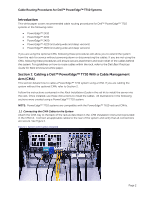
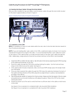
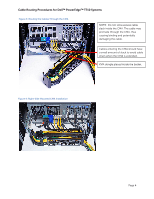
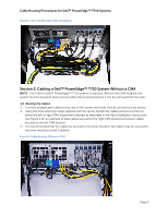
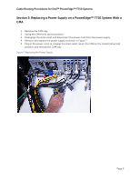
Cable Routing Procedures for Dell™ PowerEdge™ T710 Systems 1.2 Routing the Power Cables Through the Strain Reliefs After you have installed the tray and cables, route the power cables through the strain reliefs located on the power supply handles as shown in Figure 2. Figure 2: Routing Power Cables Through the Strain Reliefs 1.3 Installation of the CMA NOTE: For guidelines on how to route cables within the rack, refer to the Dell Best Practices Guide for Rack Enclosures white paper. NOTE: If you are installing fiber-optic cables in the CMA, a cable bend radius of at least 1 inch must be maintained throughout the length of the cable. It is recommended that fiber-optic cables be routed on the exterior of the cable bundle to increase the bend radius of the fiber-optic cables through the CMA. Additionally, a large amount of slack at the entrance and exit of the CMA is recommended. 1. Install the CMA on either the rear right or rear left side of the rails by attaching both CMA housings to the attachment brackets on the rails. 2. Route the cables through the CMA while avoiding twisting the cables. Use the hook and loop straps on the CMA to secure the cables. See Figure 3. 3. If the cable bundle includes a keyboard, video, and mouse (KVM) dongle, place the dongle inside the CMA basket. 4. Once you have routed all the cables through the CMA, dress the cable slack between the back of the system and the entrance of the CMA using the tie wraps (shown in yellow in all illustrations) provided in the CMA kit. 5. Clip off the excess length of material from the tie wraps. Make sure that the heads of the tie wraps are positioned so as to avoid interference with adjacent systems. Return the CMA to the closed (retracted) position. 6. Extend the system out of the rack to verify that there is sufficient slack in the cables on both ends of the CMA. See Figure 4 for an example of a completed right-side mounted CMA installation. See Figure 5 for an example of a completed left-side mounted CMA installation. Page 3
-
 1
1 -
 2
2 -
 3
3 -
 4
4 -
 5
5 -
 6
6 -
 7
7 -
 8
8
 |
 |
