Dell PowerEdge T20 Technical Guide - Page 10
Chassis features, PowerEdge T20 Systems Owner's Manual - drivers
 |
View all Dell PowerEdge T20 manuals
Add to My Manuals
Save this manual to your list of manuals |
Page 10 highlights
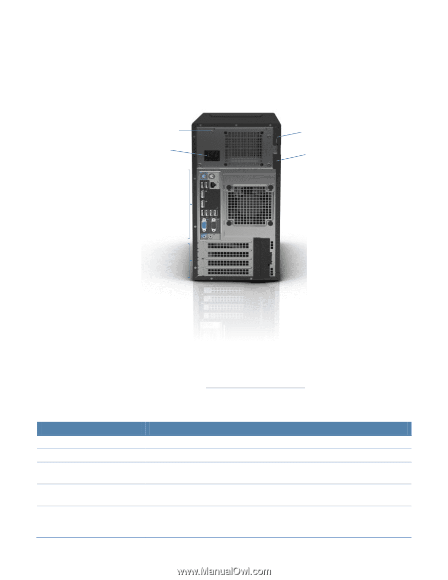
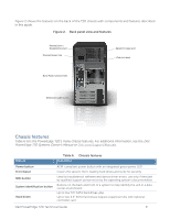
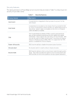
Figure 2 shows the features on the back of the T20 chassis with components and features described in this guide. Figure 2. Back panel view and features POWER SUPPLY DIAGNOSTIC LIGHT POWER CONNECTOR SECURITY CABLE SLOT PADLOCK RING BACK PANEL CONNECTORS EXPANSION CARD SLOTS Chassis features Table 6 lists the PowerEdge T20's many chassis features. For additional information, see the Dell PowerEdge T20 Systems Owner's Manual on Dell.com/Support/Manuals. Feature Table 6. Chassis features Description Power button Front bezel NMI button System identification button Hard drives ACPI-compliant power button with an integrated green power LED Covers the server's front-loading hard drives and locks for security Used to troubleshoot software and device driver errors; use only if directed by qualified support personnel or by the operating system's documentation Buttons on the back and front of a system to help identify the unit in a data center environment Up to four 3.5" SATA hard drives, plus Up to two 2.5" SATA hard drives (require expansion kits) with optional controller card Dell PowerEdge T20 Technical Guide 9
-
 1
1 -
2
-
3
-
4
-
 5
5 -
 6
6 -
 7
7 -
 8
8 -
 9
9 -
 10
10 -
 11
11 -
 12
12 -
 13
13 -
 14
14 -
 15
15 -
16
-
17
-
18
-
19
-
20
-
21
-
22
-
23
-
24
-
25
-
26
-
27
-
28
-
29
 |
 |