Dell S4148U-ON EMC Networking OS10 Enterprise Edition Storage Overview - Page 16
Data center leaf-spine networks
 |
View all Dell S4148U-ON manuals
Add to My Manuals
Save this manual to your list of manuals |
Page 16 highlights
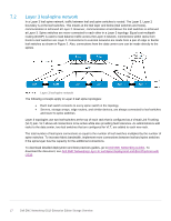
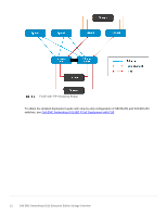
7 7.1 Data center leaf-spine networks Modern data centers are designed to optimize east-west traffic due to the increase of server-to-server communication and the rising popularity of Software Defined Storage (SDS). Leaf-spine architecture is highly scalable. As administrators add racks to the data center, a pair of leaf switches are added to each new rack. Spine switches may be added as bandwidth requirements increase. In a leaf-spine architecture, the access layer is seen as the leaf layer. Servers and storage devices connect to leaf switches at this layer. At the next level, the aggregation and core layers are condensed into a single spine layer. Every leaf switch connects to every spine switch to ensure that all leaf switches are no more than one hop away from one another. This configuration minimizes latency and the likelihood of bottlenecks in the network. Layer 2 leaf-spine network In a Layer 2 leaf-spine network, traffic between leafs and spines is switched (except for a pair of edge leafs) as shown in Figure 1. VLT is used for multipathing and load balancing traffic across the Layer 2 leaf-spine fabric. Connections from hosts to leaf switches are also Layer 2. For connections to external networks, the links between the spines and edge leafs are Layer 3. Layer 2 leaf-spine network Layer 2 topology limitations: • For each VLAN, the Layer 2 topology creates one large broadcast domain across the fabric. The Layer 3 topology has the benefit of containing broadcast domains to each rack. • The Layer 2 topology is limited to 4094 VLANs across the fabric. The Layer 3 topology allows up to 4094 VLANs per rack. • The Layer 2 topology is limited to two physical switches at the spine layer (configured as VLT peers). In a Layer 3 topology, extra spines may be added as needed to provide more paths and bandwidth. A Layer 3 topology is more scalable and is better suited for larger networks. • Overlay networks using VXLAN, such as VMware NSX, require a Layer 3 underlay network. The Layer 2 design is relatively simple. The configurations for the leafs and spines are generated by the Dell EMC Fabric Design Center. The Build-Your-Own Network design feature provides a base design for any Layer 2 network. To access the Dell EMC Fabric Design Center, go to https://fdc.emc.com. 16 Dell EMC Networking OS10 Enterprise Edition Storage Overview
-
 1
1 -
2
-
3
-
4
-
5
-
6
-
7
-
8
-
9
-
10
-
 11
11 -
 12
12 -
 13
13 -
 14
14 -
 15
15 -
 16
16 -
 17
17 -
 18
18 -
 19
19 -
 20
20 -
 21
21 -
22
-
23
-
24
-
25
 |
 |
