Dell S5000 Dell Networking Installation Guide - Page 9
Unpacking the Switch, Important Points Before You Continue
 |
View all Dell S5000 manuals
Add to My Manuals
Save this manual to your list of manuals |
Page 9 highlights
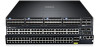
3 Unpacking the Switch The S5000 and its accessories are shipped in multiple boxes. Before unpacking the switch, inspect the container and immediately report any evidence of damage. Verify that you have received your ordered items. For example, if you order one S5000 switch, the following items are included. WARNING: If any item is missing or damaged, contact your Dell Networking representative or reseller for instructions. WARNING: Electrostatic discharge (ESD) damage can occur if components are mishandled. Always wear an ESDpreventive wrist or heel ground strap when handling the S5000 and its components. • One S5000 switch • Two Fans • Two Power Supplies (either AC or DC) • One rail kit (#1 and #2 Phillips screwdrivers required) • Screws for rack installation • Two to Four I/O Modules (according to order) • Two Blanks • One RJ-45 to DB-9 female cable • Two AC or DC power cords for AC or DC units (country/region specific) • Getting Started Guide • Safety and Regulatory Information • Warranty and Support Information • Software License Agreement 1. Place the container on a clean, flat surface and cut all straps securing the container. 2. Open the container or remove the container top. 3. Carefully remove all components from the container and place it on a secure and clean surface. 4. Remove all packing material. 5. Inspect the switch and accessories for damage. Important Points Before You Continue • Identify the I/O and Utility panel on the chassis. The I/O panel has four fixed 40GbE ports on the right side of the panel, refer to Figure 1. The Utility panel has the power supply slots, LEDs, and USB slots on the left side of the panel, refer to Figure 3. • Identify slots 0, 1, 2, and 3 on the I/O panel, refer to Figure 2. You can insert a Fibre Channel module only in slot 0. You can install the Ethernet modules in slots 0, 1, 2, and 3. • Identify slots 0, 1, 2, and 3 on the Utility panel, refer to Figure 3. You can insert Power supply units (PSUs) only in slots 0 and 3. You can insert the Fan modules in any of the slots. 9
-
 1
1 -
2
-
3
-
 4
4 -
 5
5 -
 6
6 -
 7
7 -
 8
8 -
 9
9 -
 10
10 -
 11
11 -
 12
12 -
 13
13 -
 14
14 -
15
-
16
-
17
-
18
-
19
-
20
-
21
-
22
-
23
-
24
-
25
-
26
-
27
-
28
-
29
-
30
-
31
-
32
-
33
-
34
-
35
-
36
-
37
-
38
-
39
-
40
-
41
-
42
-
43
-
44
-
45
-
46
-
47
-
48
-
49
-
50
 |
 |
