Dell STUDIO XPS 16 Service Manual - Page 43
System Board - or xps 15
 |
UPC - 067540444442
View all Dell STUDIO XPS 16 manuals
Add to My Manuals
Save this manual to your list of manuals |
Page 43 highlights
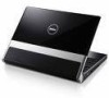
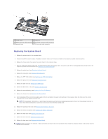
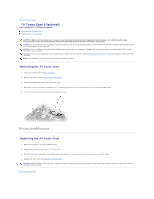
Back to Contents Page System Board Dell™ Studio XPS™ 1640 Service Manual Removing the System Board Replacing the System Board CAUTION: Before working inside your computer, read the safety information that shipped with your computer. For additional safety best practices information, see the Regulatory Compliance Homepage at www.dell.com/regulatory_compliance. NOTICE: To avoid electrostatic discharge, ground yourself by using a wrist grounding strap or by periodically touching an unpainted metal surface (such as the back panel) on the computer. NOTICE: Only a certified service technician should perform repairs on your computer. Damage due to servicing that is not authorized by Dell™ is not covered by your warranty. NOTICE: To help prevent damage to the system board, remove the main battery (see Before Working Inside Your Computer) before working inside the computer. The system board's BIOS chip contains the Service Tag, which is also visible on a barcode label on the bottom of the computer. The replacement kit for the system board includes a CD that provides a utility for transferring the Service Tag to the replacement system board. NOTICE: Handle components and cards by their edges, and avoid touching pins and contacts. Removing the System Board 1. Follow the instructions in Before You Begin. 2. Remove the base cover (see Removing the Base Cover). 3. Remove the rear caps (see Removing the Rear Caps). 4. Remove the hard drive (see Removing the Hard Drive). 5. Remove the memory module(s) (see Removing the Memory Module(s)). 6. Remove the processor heat sink (see Removing the Processor Heat Sink). 7. Remove the thermal fan (see Removing the Thermal Fan). 8. Remove the coin-cell battery (see Removing the Coin-Cell Battery). 9. Remove the Mini-Cards, if any (see Removing the Mini-Card). 10. Remove the palm rest (see Removing the Palm Rest). 11. Remove the optical drive (see Removing the Optical Drive). 12. Remove the IEEE 1394 module (see Removing the IEEE 1394 Module). 13. Remove the subwoofer (see Removing the Subwoofer). 14. Remove the audio board (see Removing the Audio Board). 15. Disconnect the right power/battery light cable, left power/battery light cable, display cable, and camera cable from the system board connectors (see Removing the Display Assembly). 16. Remove the three screws that secure the system board to the computer base. 17. Disconnect the eSATA connector cable, AC adapter connector cable, and TV tuner card cable from the respective system board connectors. 18. Lift the system board at an angle toward the side of the computer and out of the computer base.
-
 1
1 -
2
-
3
-
4
-
5
-
6
-
7
-
8
-
9
-
10
-
11
-
12
-
13
-
14
-
15
-
16
-
17
-
18
-
19
-
20
-
21
-
22
-
23
-
24
-
25
-
26
-
27
-
28
-
29
-
30
-
31
-
32
-
33
-
34
-
35
-
36
-
37
-
 38
38 -
 39
39 -
 40
40 -
 41
41 -
 42
42 -
 43
43 -
 44
44 -
 45
45 -
 46
46 -
 47
47
 |
 |