Dell Studio Hybrid Studio Desktop Service Manual - Page 21
Replacing the Front I/O Panel
 |
View all Dell Studio Hybrid Studio Desktop manuals
Add to My Manuals
Save this manual to your list of manuals |
Page 21 highlights
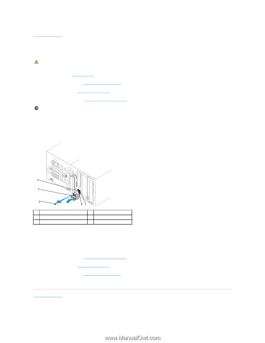
Back to Contents Page Replacing the Front I/O Panel Dell Studio™ 540 Service Manual CAUTION: Before working inside your computer, read the safety information that shipped with your computer. For additional safety best practices information, see the Regulatory Compliance Homepage at www.dell.com/regulatory_compliance. 1. Follow the procedures in Before You Begin. 2. Remove the computer cover (see Replacing the Computer Cover). 3. Remove the front panel (see Replacing the Front Panel). 4. Remove any expansion cards (see Replacing a PCI/PCI Express Card). NOTICE: Carefully note the routing of each cable before you disconnect it, so that you are sure to re-route cables correctly. An incorrectly routed or a disconnected cable could lead to computer problems. 5. Disconnect the cables connected to the I/O panel from the system board. 6. Remove the screw that secures the I/O panel to the chassis. 7. Carefully remove the existing I/O panel from the computer. 1 I/O panel clamp slot 3 screw 5 cables 2 I/O panel clamp 4 I/O panel 8. To replace a new I/O panel, align and slide the I/O panel clamp into the I/O panel clamp slot. 9. Replace the screw that secures the I/O panel to the chassis. 10. Reconnect the cables to the system board. 11. Replace any expansion cards (see Replacing a PCI/PCI Express Card). 12. Replace the front panel (see Replacing the Front Panel). 13. Replace the computer cover (see Replacing the Computer Cover). 14. Connect your computer and devices to an electrical outlet, and turn them on. Back to Contents Page
-
 1
1 -
2
-
3
-
4
-
5
-
6
-
7
-
8
-
9
-
10
-
11
-
12
-
13
-
14
-
15
-
 16
16 -
 17
17 -
 18
18 -
 19
19 -
 20
20 -
 21
21 -
 22
22 -
 23
23 -
 24
24 -
 25
25 -
 26
26 -
27
-
28
-
29
-
30
-
31
-
32
-
33
-
34
-
35
-
36
 |
 |