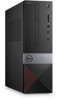
Dell Vostro 3471 Service Manual
Dell Vostro 3471 Manual
 |
View all Dell Vostro 3471 manuals
Add to My Manuals
Save this manual to your list of manuals |
Dell Vostro 3471 manual content summary:
- Dell Vostro 3471 | Service Manual - Page 1
Dell Vostro 3471 Service Manual Regulatory Model: D13S Regulatory Type: D13S003 May 2020 Rev. A01 - Dell Vostro 3471 | Service Manual - Page 2
1 Working on your computer...5 Safety instructions...5 Turning off your computer - Windows 10 card-optional...19 Installing the PCIe X1 expansion card-optional...21 Removing the PCIe X16 expansion card-optional...23 Installing the PCIe X16 expansion card-optional...25 Installing PCIe expansion card - Dell Vostro 3471 | Service Manual - Page 3
44 Installing the heat sink assembly...46 Memory modules...48 Removing the memory module...48 Installing the memory module...49 Power switch...50 Removing power Installing the system board...69 TPM 2.0 installation...74 4 Troubleshooting...77 Enhanced Pre-Boot System Assessment - ePSA diagnostics 77 - Dell Vostro 3471 | Service Manual - Page 4
of data and tells you how to avoid the problem. WARNING: A WARNING indicates a potential for property damage, personal injury, or death. © 2020 Dell Inc. or its subsidiaries. All rights reserved. Dell, EMC, and other trademarks are trademarks of Dell Inc. or its subsidiaries. Other trademarks may be - Dell Vostro 3471 | Service Manual - Page 5
only perform troubleshooting and simple repairs as authorized in your product documentation, or as directed by the online or telephone service and support team. Damage due to servicing that is not authorized by Dell is not covered by your warranty. Read and follow the safety instructions that came - Dell Vostro 3471 | Service Manual - Page 6
the back of the computer. After working inside your computer After you complete any replacement procedure, ensure that you connect any external devices, cards, and cables before turning on your computer. 1. Connect any telephone or network cables to your computer. CAUTION: To connect a network cable - Dell Vostro 3471 | Service Manual - Page 7
bus power and increased device current draw to better accommodate power-hungry devices • New power management features • Full-duplex data transfers and support for new transfer types • Backward USB 2.0 compatibility • New connectors and cable The topics below cover some of the most commonly asked - Dell Vostro 3471 | Service Manual - Page 8
3.0/USB 3.1 Gen 1 products: • External Desktop USB 3.0/USB 3.1 Gen 1 Hard Drives • • USB 3.0/USB 3.1 Gen 1 Adapter Cards & Hubs Compatibility The good news is that supported, uncompressed, all-digital audio/video interface. HDMI provides an interface between any compatible digital audio/video - Dell Vostro 3471 | Service Manual - Page 9
picture settings based on content type • Additional Color Spaces - Adds support for additional color models used in digital photography and computer graphics • 4K Support - Enables video resolutions far beyond 1080p, supporting next-generation displays that will rival the Digital Cinema systems used - Dell Vostro 3471 | Service Manual - Page 10
1 screwdriver • Phillips # 2 screwdriver • Small plastic scribe Screw size list Table 2. Vostro 3471 Component Screw type System board 6-32xL6.35 drive bracket Optical drive to optical M2x2 3 drive bracket WLAN card M2x3.5 1 Quantity Image Color Black Silver Silver Black Silver 10 - Dell Vostro 3471 | Service Manual - Page 11
) 7. ATX Power Connector(ATX_SYS) 9. Service mode / password clear/CMOS clear jumpers Fan Connector(FAN_CPU) Cover 2. M.2 connector for WIFI card 4. SATA power connector (Black) 6. SATA3 connector ( for SSD 14. CPU Power Connector(ATX_CPU) 16. Memory-module slots (DIMM1, DIMM2) Removing the cover - Dell Vostro 3471 | Service Manual - Page 12
c. Lift and remove the cover from the computer . 12 Removing and installing components - Dell Vostro 3471 | Service Manual - Page 13
Installing the cover 1. Slide the cover from the back of the computer, until the latches snap-in [1]. 2. Replace the two 6-32xL6.35 screws to secure the cover [2]. 3. Follow the procedures in After Working Inside Your Computer Front Bezel Removing the front bezel 1. Follow the procedure in Before - Dell Vostro 3471 | Service Manual - Page 14
b. Rotate the front bezel away from the computer [1] and pull to release the tabs on the front bezel from the front-panel slots [2]. 14 Removing and installing components - Dell Vostro 3471 | Service Manual - Page 15
Installing the front bezel 1. Hold the bezel and ensure that the hooks on the tabs snap into the notches on the computer [1]. 2. Rotate the front bezel toward the front of the computer [2]. Removing and installing components 15 - Dell Vostro 3471 | Service Manual - Page 16
3. Press the front bezel until the tabs snap in. 16 Removing and installing components - Dell Vostro 3471 | Service Manual - Page 17
4. Install the cover. 5. Follow the procedure in After Working Inside Your Computer. Cooling shroud Removing the cooling shroud 1. Follow the procedure in Before working inside your computer. 2. Remove the cover 3. Follow the steps to remove the heat sink fan cover: a. Pry the plastic notches that - Dell Vostro 3471 | Service Manual - Page 18
Installing the cooling shroud 1. Align the tabs on the cooling shroud with the securing slots on the computer. 2. Lower the cooling shroud into the chassis until the notches secure with a click sound and the cooling shroud is firmly seated. 18 Removing and installing components - Dell Vostro 3471 | Service Manual - Page 19
the rear side of the system. 3. Install the cover. 4. Follow the procedure in After Working Inside Your Computer. Expansion card Removing the PCIe X1 expansion card-optional 1. Follow the procedure in Before working inside your computer. 2. Remove the cover. 3. Perform the following steps to remove - Dell Vostro 3471 | Service Manual - Page 20
b. Remove the expansion card from the slot on the computer 20 Removing and installing components - Dell Vostro 3471 | Service Manual - Page 21
Installing the PCIe X1 expansion card-optional 1. Insert the expansion card on the slot. Removing and installing components 21 - Dell Vostro 3471 | Service Manual - Page 22
2. Push the metal tab until it snaps in place. 22 Removing and installing components - Dell Vostro 3471 | Service Manual - Page 23
Follow the procedure in After Working Inside Your Computer. Removing the PCIe X16 expansion card-optional 1. Follow the procedure in Before working inside your computer. 2. Remove the cover. 3. Perform the following steps to remove the expansion card: a. Pull the metal tab to release the expansion - Dell Vostro 3471 | Service Manual - Page 24
b. Pull the card-retention tab [1], and remove the expansion card from the slot on the computer [2]. 24 Removing and installing components - Dell Vostro 3471 | Service Manual - Page 25
Installing the PCIe X16 expansion card-optional 1. Insert the expansion card on the slot [1]. 2. Push the card-retention latch to secure the expansion card [2]. Removing and installing components 25 - Dell Vostro 3471 | Service Manual - Page 26
3. Push the metal tab until it snaps in place. 26 Removing and installing components - Dell Vostro 3471 | Service Manual - Page 27
4. Install the cover 5. Follow the procedure in After Working Inside Your Computer. Installing PCIe expansion card in slot 1- optional 1. Pull the release latch to open . Removing and installing components 27 - Dell Vostro 3471 | Service Manual - Page 28
2. To remove the PCIe bracket as shown below, insert a flathead screwdriver in the hole of PCIe bracket [1], and repeatedly spin screwdriver from 0-45 degrees to release the bracket [2]. 28 Removing and installing components - Dell Vostro 3471 | Service Manual - Page 29
3. Insert the PCIe expansion card to the connector on the system board. Removing and installing components 29 - Dell Vostro 3471 | Service Manual - Page 30
4. Close the release latch. 5. Install the: a. cover 6. Follow the procedure in After working inside your computer. 3.5-inch hard drive chassis Removing the 3.5-inch hard drive chassis 1. Follow the procedure in Before working inside your computer. 2. Remove the: a. cover b. front bezel 3. - Dell Vostro 3471 | Service Manual - Page 31
5. Slide the 3.5-inch hard drive chassis and lift it from the system. Removing and installing components 31 - Dell Vostro 3471 | Service Manual - Page 32
Installing the 3.5-inch hard drive chassis 1. Slide the 3.5-inch hard drive chassis into the drive bay. 32 Removing and installing components - Dell Vostro 3471 | Service Manual - Page 33
2. Replace the two 6-32xL3.5 screws to secure the 3.5-inch hard drive chassis to the computer [1]. 3. Connect the data and power cables to the hard drive [2]. Removing and installing components 33 - Dell Vostro 3471 | Service Manual - Page 34
4. Install: a. front bezel b. cover 5. Follow the procedures in After Working Inside Your Computer. 3.5-inch hard drive Removing the 3.5-inch hard drive from the hard drive bracket 1. Follow the procedures in Before Working Inside Your Computer. 2. Remove: a. cover b. front bezel c. 3.5-inch hard - Dell Vostro 3471 | Service Manual - Page 35
Installing the 3.5-inch hard drive into the hard drive bracket 1. Slide the hard drive into the hard drive bracket [1]. 2. Replace the two 6-32xL3.6 screws to secure the hard drive to the bracket [2]. 3. Install: a. 3.5-inch hard drive chassis b. front bezel c. cover 4. Follow the procedure in - Dell Vostro 3471 | Service Manual - Page 36
Drive cage Removing the drive cage 1. Follow the procedure in Before working inside your computer. 2. Remove the: a. cover b. front bezel c. cooling shroud d. 3.5-inch hard drive chassis 3. Follow the steps to release the drive cage: a. Remove the 6-32xL6.35 screw that secures the drive cage to the - Dell Vostro 3471 | Service Manual - Page 37
Installing the drive cage 1. Place the drive cage in the chassis [1] and connect the data and power cables to the optical drive [2]. Removing and installing components 37 - Dell Vostro 3471 | Service Manual - Page 38
2. Insert the drive cage into the slot until it clicks into place [1]. 3. Replace the 6-32xL6.35 screw to secure the drive cage to the chassis [2]. 38 Removing and installing components - Dell Vostro 3471 | Service Manual - Page 39
4. Install the: a. 3.5-inch hard drive chassis b. cooling shroud c. front bezel d. cover 5. Follow the procedure in After Working Inside Your Computer. Optical drive Removing the optical drive 1. Follow the procedure in Before working inside your computer. 2. Remove the: a. cover b. front bezel c. - Dell Vostro 3471 | Service Manual - Page 40
Installing the optical drive 1. Slide the optical drive into the drive bay until it snaps [1]. 2. Tighten the three M2x2 screws to secure the optical drive to the bracket [2]. 3. Install the: a. drive cage b. 3.5-inch hard drive chassis c. cooling shroud d. front bezel e. cover 4. Follow the - Dell Vostro 3471 | Service Manual - Page 41
M.2 SATA SSD Removing M.2 SATA SSD 1. Follow the procedure in Before working inside your computer. 2. Remove the: a. cover 3. To remove the M.2 SATA SSD: a. Pull the blue tab that secures the M.2 SATA SSD to the system board [1]. b. Slide out the M.2 SATA SSD from the connector on the system board - Dell Vostro 3471 | Service Manual - Page 42
the computer: a. Remove the M2L3.5 screw to release the plastic tab that secures the WLAN card to the computer [1, 2]. b. Disconnect the WLAN cables from the connectors on the WLAN card [3]. c. Remove the WLAN card from its connector on the system board [4]. 42 Removing and installing components - Dell Vostro 3471 | Service Manual - Page 43
Installing the WLAN card 1. Insert the WLAN card to the connector on the system board [1]. 2. Connect the WLAN cables to the connectors on the WLAN card[ 2] . 3. Place the plastic tab and tighten the M2x3.5 screw to secure the WLAN card to the system board [3]. Removing and installing components - Dell Vostro 3471 | Service Manual - Page 44
4. Install: a. drive cage b. 3.5-inch hard drive chassis c. cooling shroud d. front bezel e. cover 5. Follow the procedure in After Working Inside Your Computer. Heat sink assembly Removing the heat sink assembly 1. Follow the procedure in Before working inside your computer. 2. Remove the: a. cover - Dell Vostro 3471 | Service Manual - Page 45
b. Remove the screws securing the heatsink assembly in a sequential order [1,2,3,4]. c. Lift the heat sink and remove it from the chassis. Removing and installing components 45 - Dell Vostro 3471 | Service Manual - Page 46
Installing the heat sink assembly 1. Place the heat sink assembly in the slot by aligning with the screw holders. 2. Tighten the screws in a sequential order to secure the heat sink assembly to the system board [1,2,3,4]. 46 Removing and installing components - Dell Vostro 3471 | Service Manual - Page 47
3. Connect the heat sink assembly cable to the connector on the system board. Removing and installing components 47 - Dell Vostro 3471 | Service Manual - Page 48
cover b. front bezel c. 3.5-inch hard drive chassis d. drive cage e. Cooling shroud 3. To remove the front memory module: a. Pull the clips securing the memory module until the memory module pops up [1]. b. Remove the memory module from the system board [2]. 48 Removing and installing components - Dell Vostro 3471 | Service Manual - Page 49
Installing the memory module 1. Insert the memory module into the memory module socket until the clips secure the memory module. Removing and installing components 49 - Dell Vostro 3471 | Service Manual - Page 50
2. Install the: . a. cooling shroud b. drive cage c. 3.5-inch hard drive chassis d. front bezel e. cover 3. Follow the procedure in After working inside your computer. Power switch Removing power switch 1. Follow the procedure in Before working inside your computer. 2. Remove the: a. cover b. front - Dell Vostro 3471 | Service Manual - Page 51
a. Remove the 6-32xL6.35 screw that secures the IO bracket [1] to the chassis and open the IO bracket[2]. b. Disconnect the power switch cable from the connector on the system board [1]. c. Press the power switch retention tabs [2] and pull the power switch out from the computer [3]. Removing and - Dell Vostro 3471 | Service Manual - Page 52
Installing the power switch 1. Slide the power switch module into the slot on the chassis until it clicks into place [1]. 2. Connect the power switch cable to the connector on the system board [2]. 52 Removing and installing components - Dell Vostro 3471 | Service Manual - Page 53
3. Push the IO bracket until it secures to the chassis [1]. 4. Replace the 6-32xL6.35 screw to secure the IO bracket to the system [2]. Removing and installing components 53 - Dell Vostro 3471 | Service Manual - Page 54
5. Install the: a. drive cage b. 3.5-inch hard drive chassis c. front bezel d. cover 6. Follow the procedure in After working inside your computer. Power supply unit Removing the power supply unit PSU 1. Follow the procedure in Before working inside your computer. 2. Remove the: a. cover b. front - Dell Vostro 3471 | Service Manual - Page 55
4. Perform the following steps to remove the PSU: a. Remove the three 6-32xL6.35 screws that secure the PSU [1]. b. Press the blue release tab to release the PSU [2]. Removing and installing components 55 - Dell Vostro 3471 | Service Manual - Page 56
c. Slide and lift the PSU from the computer. 56 Removing and installing components - Dell Vostro 3471 | Service Manual - Page 57
Installing the power supply unit PSU 1. Slide the PSU towards the back of the computer until it snaps into place. Removing and installing components 57 - Dell Vostro 3471 | Service Manual - Page 58
2. Replace the three 6-32xL6.35 screws to secure the power supply unit to the computer. 58 Removing and installing components - Dell Vostro 3471 | Service Manual - Page 59
3. Route the PSU cables through the placeholder. 4. Connect the PSU cables to their connectors on the system board. Removing and installing components 59 - Dell Vostro 3471 | Service Manual - Page 60
5. Install the: a. drive cage b. 3.5-inch hard drive chassis c. cooling shroud d. front bezel e. cover 6. Follow the procedure in After Working Inside Your Computer. Coin-cell battery Removing the coin cell battery 1. Follow the procedures in Before working inside your computer. 2. Remove the: a. - Dell Vostro 3471 | Service Manual - Page 61
Installing the coin cell battery 1. Place the coin cell battery in its slot on the system board [1] and press until it snaps in place [2].. Removing and installing components 61 - Dell Vostro 3471 | Service Manual - Page 62
2. Install the: a. drive cage b. 3.5-inch hard drive chassis c. cooling shroud d. front bezel e. cover 3. Follow the procedures in After Working Inside Your Computer. Processor Removing the processor 1. Follow the procedure in Before working inside your computer. 2. Remove the: a. cover b. cooling - Dell Vostro 3471 | Service Manual - Page 63
CAUTION: The processor socket pins are fragile and can be permanently damaged. Be careful not to bend the pins in the processor socket when removing the processor out of the socket. b. Lift the processor cover [2], remove the processor from the socket and place it in an antistatic bag [3]. - Dell Vostro 3471 | Service Manual - Page 64
board Removing the system board 1. Follow the procedure in Before working inside your computer. 2. Remove the a. cover b. front bezel c. 3.5-inch hard drive chassis d. drive cage e. memory module f. cooling shroud g. expansion card (optional) 64 Removing and installing components - Dell Vostro 3471 | Service Manual - Page 65
h. M.2 SATA SSD i. heat sink assembly j. WLAN card 3. Follow the steps to open the IO bracket: a. Remove the 6-32xL6.35 screw that secures the IO bracket to the chassis [1]. b. Pull the IO bracket - Dell Vostro 3471 | Service Manual - Page 66
5. Follow the steps to remove the system board: a. Remove the six 6-32xL6.35 screws that secure system board to the chassis. 66 Removing and installing components - Dell Vostro 3471 | Service Manual - Page 67
b. Pull the system board towards the front of the system. Removing and installing components 67 - Dell Vostro 3471 | Service Manual - Page 68
c. Lift the system board from the chassis. 68 Removing and installing components - Dell Vostro 3471 | Service Manual - Page 69
Installing the system board 1. Insert the system board and ensure that ports are aligned to the holes on the back panel. NOTE: Make sure to open the IO bracket before placing the system board in the system. Removing and installing components 69 - Dell Vostro 3471 | Service Manual - Page 70
2. Push the system board towards the rear side of the system. 70 Removing and installing components - Dell Vostro 3471 | Service Manual - Page 71
3. Replace the six 6-32xL6.35 screws to secure the system board. Removing and installing components 71 - Dell Vostro 3471 | Service Manual - Page 72
4. Connect the following cables to the system board- PSU cable [1], power switch cable [2], HDD SATA cable and HDD/ODD power cable [3], ODD SATA cable and PSU cable [4]. 72 Removing and installing components - Dell Vostro 3471 | Service Manual - Page 73
5. Close the IO bracket [1] and replace the 6-32xL6.35 screw to secure the IO bracket to the chassis [2]. Removing and installing components 73 - Dell Vostro 3471 | Service Manual - Page 74
chassis g. cooling shroud h. memory module i. front bezel j. cover 7. Follow the procedures in After Working Inside Your Computer. TPM 2.0 installation When you replace the system board for Windows 10 systems, the TPM 2.0 utility needs to be downloaded from Dell.com/support and updated. The act of - Dell Vostro 3471 | Service Manual - Page 75
a. Boot to Windows. b. Launch the PowerShell Command window in Administrator mode. c. At the Powershell command prompt, execute the command: > Disable-TpmAutoProvisioning. d. Confirm the following results:- AutoProvisioning: Disabled. e. Reboot the system, to BIOS Setup by pressing F2. f. Navigate - Dell Vostro 3471 | Service Manual - Page 76
NOTE: The Enable Legacy Option ROMs option should be disabled to make the above setting. 76 Removing and installing components - Dell Vostro 3471 | Service Manual - Page 77
on the computer. 2. As the computer boots, press the F12 key when the Dell logo is displayed. 3. In the boot menu screen, use Up/Down arrow key Problem System board Problem Description System board failure 2, 2 System board, PSU, or cabling System board, PSU, or cabling failure Troubleshooting - Dell Vostro 3471 | Service Manual - Page 78
board 3, 5 Memory 3, 6 BIOS 3, 7 BIOS Problem Description System board, memory, or CPU failure Coin-cell battery failure Corrupt BIOS. Recovery image is not found or is invalid during auto BIOS recovery process. CPU configuration error or CPU failure Memory failure PCI or video card / chip - Dell Vostro 3471 | Service Manual - Page 79
disk. Do not use these characters in filenames. A memory module may be loose. Reinstall the memory module or, if necessary, replace it. The operating system and restart the computer. If the problem persists, try another drive. Run the Hard Disk Drive tests in Dell Diagnostics. The hard drive does not - Dell Vostro 3471 | Service Manual - Page 80
ENOUGH MEMORY OR Support for instructions (click Start > Help and Support Dell. The reserve battery that supports the system configuration settings may require recharging. Connect your computer to an electrical outlet to charge the battery. If the problem persists, Contact Dell. 80 Troubleshooting - Dell Vostro 3471 | Service Manual - Page 81
operating range. Dell recommends that you back up your data regularly. A parameter out of range may or may not indicate a potential hard drive problem A chip on the system board might be malfunctioning or motherboard failure. S.M.A.R.T error, possible hard disk drive failure. Troubleshooting 81 - Dell Vostro 3471 | Service Manual - Page 82
options. Availability varies by country and product, and some services may not be available in your area. To contact Dell for sales, technical support, or customer service issues: 1. Go to Dell.com/support. 2. Select your support category. 3. Verify your country or region in the Choose a Country
-
 1
1 -
 2
2 -
 3
3 -
 4
4 -
 5
5 -
 6
6 -
 7
7 -
8
-
9
-
10
-
11
-
12
-
13
-
14
-
15
-
16
-
17
-
18
-
19
-
20
-
21
-
22
-
23
-
24
-
25
-
26
-
27
-
28
-
29
-
30
-
31
-
32
-
33
-
34
-
35
-
36
-
37
-
38
-
39
-
40
-
41
-
42
-
43
-
44
-
45
-
46
-
47
-
48
-
49
-
50
-
51
-
52
-
53
-
54
-
55
-
56
-
57
-
58
-
59
-
60
-
61
-
62
-
63
-
64
-
65
-
66
-
67
-
68
-
69
-
70
-
71
-
72
-
73
-
74
-
75
-
76
-
77
-
78
-
79
-
80
-
81
-
82
 |
 |
Dell Vostro 3471
Service Manual
Regulatory Model: D13S
Regulatory Type: D13S003
May 2020
Rev. A01