Dell Vostro 3580 Service Manual
Dell Vostro 3580 Manual
 |
View all Dell Vostro 3580 manuals
Add to My Manuals
Save this manual to your list of manuals |
Dell Vostro 3580 manual content summary:
- Dell Vostro 3580 | Service Manual - Page 1
Dell Vostro 3580 Service Manual Regulatory Model: P75F Regulatory Type: P75F010 - Dell Vostro 3580 | Service Manual - Page 2
of data and tells you how to avoid the problem. WARNING: A WARNING indicates a potential for property damage, personal injury, or death. © 2019 Dell Inc. or its subsidiaries. All rights reserved. Dell, EMC, and other trademarks are trademarks of Dell Inc. or its subsidiaries. Other trademarks may be - Dell Vostro 3580 | Service Manual - Page 3
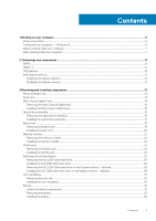
Contents 1 Working on your computer...6 Safety instructions...6 Turning off your computer - Windows 10...6 Before battery...29 Removing the coin-cell...29 Installing the coin-cell battery...30 Battery...31 Lithium-ion battery precautions...31 Removing the battery...32 Installing the battery... - Dell Vostro 3580 | Service Manual - Page 4
Hard drive...33 Removing the hard drive assembly...33 Installing the hard drive assembly...35 System fan...37 Removing the system fan...37 Installing the system fan...39 Heat sink...41 Removing the heatsink...41 Installing the heatsink...41 VGA Daughterboard...42 Removing the VGAcable...42 - Dell Vostro 3580 | Service Manual - Page 5
-rest and keyboard assembly...85 Removing the palmrest and keyboard assembly...85 4 Troubleshooting...87 Enhanced Pre-Boot System Assessment (ePSA) diagnostics 87 Running the ePSA options...89 WiFi power cycle...89 Flea power release...89 5 Getting help...90 Contacting Dell...90 Contents 5 - Dell Vostro 3580 | Service Manual - Page 6
only perform troubleshooting and simple repairs as authorized in your product documentation, or as directed by the online or telephone service and support team. Damage due to servicing that is not authorized by Dell is not covered by your warranty. Read and follow the safety instructions that came - Dell Vostro 3580 | Service Manual - Page 7
task To avoid damaging your computer, perform the following steps before you begin working inside the computer. Steps 1. Ensure that you follow the Safety Instruction. 2. Ensure that your work surface is flat and clean to prevent the computer cover from being scratched. 3. Turn off your computer - Dell Vostro 3580 | Service Manual - Page 8
2 Technology and components NOTE: Instructions provided in this section are applicable on computers shipped 1.2 volts, compared to DDR3 which requires 1.5 volts of electrical power to operate. DDR4 also supports a new, deep power-down mode that allows the host device to go into standby without - Dell Vostro 3580 | Service Manual - Page 9
code. If all memory fails, the LCD does not turn on. Troubleshoot for possible memory failure by trying known good memory modules in the primary advantage is cable reduction and content protection provisions. HDMI supports standard, enhanced, or high-definition video, plus multichannel digital - Dell Vostro 3580 | Service Manual - Page 10
and peripheral devices like mice, keyboards, external drivers, and printers. Let's take a quick look features • Full-duplex data transfers and support for new transfer types • Backward USB defined by the latest USB 3.0/USB 3.1 Gen 1 specification. They are Super-Speed, Hi-Speed and FullSpeed. The - Dell Vostro 3580 | Service Manual - Page 11
continue to require separate drivers for USB 3.0/USB 3.1 Gen 1 controllers. Intel Optane memory Intel Optane memory functions only as a storage accelerator. It neither replaces nor adds to the memory (RAM) installed on your computer. NOTE: Intel Optane memory is supported on computers that meet - Dell Vostro 3580 | Service Manual - Page 12
Generation or higher Intel Core i3/i5/i7 processor • Windows 10 64-bit version 1607 or higher • Intel Rapid Storage Technology driver version 15.9.1.1018 or higher Table 2. Intel Optane memory specifications Feature Interface Connector Configurations supported Capacity Specifications PCIe 3x2 NVMe - Dell Vostro 3580 | Service Manual - Page 13
screwdriver • Plastic scribe NOTE: The #0 screw driver is for screws 0-1 and the #1 screw driver is for screws 2-4. Screw list The table M2x2 2 NOTE: Screw color may vary depending on the configuration ordered. Battery M2x3 4 Solid-state drive to thermal plate M2x2 Big Head 1 Solid- - Dell Vostro 3580 | Service Manual - Page 14
Card Removing the Micro Secure Digital card Prerequisites 1. Follow the procedure in Before working inside your computer Steps 1. Push the micro secure digital card to release it from the computer. 2. Slide the micro secure digital card out of the computer. 14 Removing and installing components - Dell Vostro 3580 | Service Manual - Page 15
Installing the Micro Secure Digital card Steps 1. Slide the micro secure digital into the slot until it clicks into place. 2. Follow the procedures in After working inside your computer. Removing and installing components 15 - Dell Vostro 3580 | Service Manual - Page 16
Optical drive assembly Removing the optical drive assembly Prerequisites 1. Follow the procedure in before working inside your computer 2. Remove the SD memory card Steps 1. Remove the single (M2x4) screw that secures the optical drive to the system [1]. 2. Slide the optical drive out of the - Dell Vostro 3580 | Service Manual - Page 17
3. Remove the two (M2x3) screws that secure the optical drive bracket to the optical drive [1]. 4. Remove the optical drive bracket from the optical drive [2]. Installing the optical drive assembly Steps 1. Align the optical drive bracket to the screw holes on the optical drive [1]. 2. Replace the - Dell Vostro 3580 | Service Manual - Page 18
3. Insert the optical drive into the slot until it clicks into place [1]. 4. Replace the single (M2x4) screw that secures the optical drive to the system [2]. Next steps 1. Replace the SD memory card 2. Follow the procedure in after working inside your computer 18 Removing and installing - Dell Vostro 3580 | Service Manual - Page 19
Base cover Removing the base cover Prerequisites 1. Follow the procedure in before working inside your computer 2. Remove the SD memory card 3. Remove the optical drive assembly Steps 1. Loosen the three captive screws [1]. 2. Remove the single (M2x4) screw, two (M2x2) screws, and six (M2.5x7) - Dell Vostro 3580 | Service Manual - Page 20
Installing the base cover Steps 1. Place the base cover on the palmrest and keyboard assembly [1]. 2. Press the right side of the base cover until it snaps into place [2, 3]. 20 Removing and installing components - Dell Vostro 3580 | Service Manual - Page 21
3. Tighten the three captive screws, and replace the single (M2x4) screw that secures the base cover to the palmrest and keyboard assembly [1, 2]. 4. Replace the two (M2x2) screws, and six (M2.5x7) screws that secure the base cover to the palmrest and keyboard assembly [3, 4]. Removing and - Dell Vostro 3580 | Service Manual - Page 22
in before working inside your computer 2. Remove the SD memory card 3. Remove the optical drive assembly 4. Remove the base cover 5. Disconnect the battery cable from the connector on the system board. Steps 1. Pry the clips securing the memory module until the memory module pops-up [1]. 2. Remove - Dell Vostro 3580 | Service Manual - Page 23
procedure in before working inside your computer 2. Remove the SD memory card 3. Remove the optical drive assembly 4. Remove the base cover 5. Disconnect the battery cable from the connector on the system board. Steps 1. Remove the single (M2x3) screw that secures the WLAN card bracket to the system - Dell Vostro 3580 | Service Manual - Page 24
Installing the WLAN card About this task CAUTION: To avoid damage to the WLAN card, do not place any cables under it. Steps 1. Insert the WLAN card into the connector on the system board [1]. 2. Connect the WLAN cables to the connectors on the WLAN card [2]. 3. Place the WLAN card bracket to secure - Dell Vostro 3580 | Service Manual - Page 25
in before working inside your computer 2. Remove the SD memory card 3. Remove the optical drive assembly 4. Remove the base cover 5. Disconnect the battery cable from the connector on the system board. Steps 1. Loosen the captive screw that secures the thermal plate to the palmrest and keyboard - Dell Vostro 3580 | Service Manual - Page 26
4. Turn the thermal plate over. 5. Remove the single (M2x2) screw that secures the solid-state drive to the thermal plate [1]. 6. Lift the solid-state drive off the thermal plate [2]. Installing the M.2 2230 Solid-state drive Steps 1. Place the solid-state drive into the thermal plate slot [1]. 2. - Dell Vostro 3580 | Service Manual - Page 27
assembly [2]. 6. Replace the single (M2x3) screw that secures the thermal plate to the palmrest and keyboard assembly [3]. Next steps 1. Connect the battery cable to the connector on the system board. 2. Replace the base cover 3. Replace the optical drive assembly 4. Replace the SD memory card - Dell Vostro 3580 | Service Manual - Page 28
in before working inside your computer 2. Remove the SD memory card 3. Remove the optical drive assembly 4. Remove the base cover 5. Disconnect the battery cable from the connector on the system board. Steps 1. Loosen the captive screw that secures the thermal plate to the palmrest and keyboard - Dell Vostro 3580 | Service Manual - Page 29
cover 3. Replace the optical drive assembly 4. Replace the SD memory card 5. Follow the procedure in after working inside your computer Coin-cell battery Removing the coin-cell Prerequisites 1. Follow the procedure in before working inside your computer 2. Remove the SD memory card 3. Remove the - Dell Vostro 3580 | Service Manual - Page 30
Installing the coin-cell battery Steps 1. With the positive-side facing up, insert the coin-cell battery into the battery socket on the I/O board [1]. 2. Press the battery until it clicks into place [2]. 30 Removing and installing components - Dell Vostro 3580 | Service Manual - Page 31
, do not try to release it as puncturing, bending, or crushing a lithium-ion battery can be dangerous. In such an instance, contact Dell technical support for assistance. See www.dell.com/contactdell. • Always purchase genuine batteries from www.dell.com or authorized Dell partners and resellers - Dell Vostro 3580 | Service Manual - Page 32
board [1]. 2. Remove the four (M2x3) screws that secure the battery to the palmrest and keyboard assembly [2]. 3. Lift the battery off the palmrest and keyboard assembly [3]. Installing the battery Steps 1. Align the screw holes on the battery with the screw holes on the palmrest and keyboard - Dell Vostro 3580 | Service Manual - Page 33
procedure in before working inside your computer 2. Remove the SD memory card 3. Remove the optical drive assembly 4. Remove the base cover 5. Remove the battery Steps 1. Lift the latch and disconnect the hard drive cable from the system board [1]. 2. Remove the four (M2x3) screws that secure the - Dell Vostro 3580 | Service Manual - Page 34
4. Disconnect the interposer from the hard drive. 5. Remove the four (M3x3) screws that secure the hard drive bracket to the hard drive [1]. 6. Lift the hard drive bracket off the hard drive [2]. 34 Removing and installing components - Dell Vostro 3580 | Service Manual - Page 35
Installing the hard drive assembly Steps 1. Align the screw holes on the hard drive bracket with the screw holes on the hard drive [1]. 2. Replace the four (M3x3) screws that secure the hard drive bracket to the hard drive [2]. 3. Connect the interposer to the hard drive. Removing and installing - Dell Vostro 3580 | Service Manual - Page 36
assembly [2]. 6. Connect the hard drive cable to the system board and close the latch to secure the cable [3]. Next steps 1. Replace the battery 2. Replace the base cover 3. Replace the optical drive assembly 4. Replace the SD memory card 5. Follow the procedure in after working inside your - Dell Vostro 3580 | Service Manual - Page 37
the procedure in before working inside your computer 2. Remove the SD memory card 3. Remove the optical drive assembly 4. Remove the base cover 5. Disconnect the battery cable from the connector on the system board. Steps 1. Disconnect the ODD cable, display cable and fan cable from the system board - Dell Vostro 3580 | Service Manual - Page 38
3. Remove the three (M2.5x5) screws that secure the fan to the palm rest and keyboard board assembly [1]. 4. Lift the fan off the palm rest and keyboard board assembly [2]. 38 Removing and installing components - Dell Vostro 3580 | Service Manual - Page 39
[1]. 2. Replace the three (M2.5x5) screws that secure the fan to the palm rest and keyboard board assembly [2]. 3. Route the display cable through the routing guides on the fan [1]. Removing and installing components 39 - Dell Vostro 3580 | Service Manual - Page 40
4. Connect the ODD cable, display cable and fan cable to the system board [3,2,1]. Next steps 1. Replace the battery 2. Replace the base cover 3. Replace the optical drive assembly 40 Removing and installing components - Dell Vostro 3580 | Service Manual - Page 41
in before working inside your computer 2. Remove the SD memory card 3. Remove the optical drive assembly 4. Remove the base cover 5. Disconnect the battery cable from the connector on the system board. Steps 1. Loosen the four captive screws that secure the heatsink to the system board [1]. NOTE - Dell Vostro 3580 | Service Manual - Page 42
secure the heatsink to the system board [3]. Next steps 1. Connect the battery cable to the connector on the system board. 2. Replace the base Remove the optical drive assembly 4. Remove the base cover 5. Disconnect the battery cable from the connector on the system board. 6. Remove the memory 7. - Dell Vostro 3580 | Service Manual - Page 43
13. Remove the IO board 14. Remove the display assembly 15. Remove the system board Steps Disconnect the VGA cable and remove it from the palmrest and keyboard assembly [1]. Installing the VGA cable Steps Connect the VGA cable and affix it to the palmrest and keyboard assembly [1]. Removing and - Dell Vostro 3580 | Service Manual - Page 44
4. Replace the heatsink 5. Replace the system fan 6. Replace the hard drive assembly 7. Replace the coin cell battery 8. Replace the SSD 9. Replace the WLAN 10. Replace the memory 11. Connect the battery cable to the connector on the system board. 12. Replace the base cover 13. Replace the optical - Dell Vostro 3580 | Service Manual - Page 45
posts and rubber grommets, place the speakers in the slots on the palm rest and keyboard assembly [1]. 2. Route the speaker cable through the routing guides on the palm rest and keyboard assembly [2]. 3. Connect the speaker cable to the system board [3]. Removing and installing components 45 - Dell Vostro 3580 | Service Manual - Page 46
in before working inside your computer 2. Remove the SD memory card 3. Remove the optical drive assembly 4. Remove the base cover 5. Remove the battery 6. Remove the hard drive assembly Steps 1. Disconnect the VGA cable from the I/O board [1]. 2. Open the latch and disconnect the I/O board cable - Dell Vostro 3580 | Service Manual - Page 47
assembly [2]. NOTE: When the IO board cable is disconnected from the system board, an RTC error occurs. This error occurs whenever the RTC/coin-cell battery, IO board, or system board are removed. In such instances, after the system is reassembled, it will undergo and RTC reset cycle and the - Dell Vostro 3580 | Service Manual - Page 48
An "Invalid Configuration" error message is displayed prompting you to enter the BIOS and configure the date and time. The computer starts functioning normally after setting the date and time. Installing the IO board Steps 1. Using the alignment posts, place the I/O board on the palm rest and - Dell Vostro 3580 | Service Manual - Page 49
steps 1. Replace the hard drive assembly 2. Replace the battery 3. Replace the base cover 4. Replace the optical drive memory card 3. Remove the optical drive assembly 4. Remove the base cover 5. Remove the battery Steps 1. Open the latch and disconnect the hard drive cable and touch pad cable from - Dell Vostro 3580 | Service Manual - Page 50
3. Remove the two (M2x2) screws that secure the touch pad bracket to the palmrest and keyboard assembly [1]. 4. Lift the touch pad bracket off the palm rest and keyboard assembly [2]. 5. Remove the four (M2x2) screws that secure the touch pad to the palmrest and keyboard assembly [1]. 6. Lift the - Dell Vostro 3580 | Service Manual - Page 51
Installing the touch pad assembly About this task NOTE: Ensure that the touch pad is aligned with the guides available on the palm-rest and keyboard assembly, and the gap on either sides of the touch pad is equal. Steps 1. Place the touch pad - Dell Vostro 3580 | Service Manual - Page 52
3. Place the touch pad bracket into the slot on the palmrest and keyboard assembly [1]. 4. Replace the two screws (M2x2) that secure the touch pad bracket to the palmrest and keyboard assembly [2]. 5. Affix the tape that secures the touch pad to the palmrest and keyboard assembly [1]. 6. Slide the - Dell Vostro 3580 | Service Manual - Page 53
3. Remove the optical drive assembly 4. Remove the base cover 5. Disconnect the battery cable from the connector on the system board 6. Remove the WLAN Steps 1. Open Unroute the display cable from the routing guides on the palmrest and keyboard assembly [4]. Removing and installing components 53 - Dell Vostro 3580 | Service Manual - Page 54
4. Remove the five (M2.5x5) screws that secure the left and right hinges to the system board, and palmrest and keyboard assembly [1]. 5. Lift the palmrest and keyboard assembly at an angle [2]. 6. Lift the hinges. Remove the palmrest and keyboard assembly off the display assembly [1, 2] 54 - Dell Vostro 3580 | Service Manual - Page 55
7. After performing all the preceding steps, you are left with display assembly. Removing and installing components 55 - Dell Vostro 3580 | Service Manual - Page 56
Installing the display assembly About this task NOTE: Ensure that the hinges are opened to the maximum before replacing the display assembly on the palmrest and keyboard assembly. Steps 1. Align and place the palmrest and keyboard assembly under the hinges on the display assembly [1]. 2. Seat the - Dell Vostro 3580 | Service Manual - Page 57
5. Route the display cable through the routing guides on the palmrest and keyboard assembly [1]. 6. Affix the antenna cables to the system board [2]. 7. Connect the display cable and the optical drive cable to the connector on the system board [3, 4]. Removing and installing components 57 - Dell Vostro 3580 | Service Manual - Page 58
in before working inside your computer 2. Remove the SD memory card 3. Remove the optical drive assembly 4. Remove the base cover 5. Disconnect the battery cable from the connector on the system board. 6. Remove the WLAN 7. Remove the system fan 8. Remove the display assembly Steps 1. Open the - Dell Vostro 3580 | Service Manual - Page 59
and close the latch to secure the cable [4]. Next steps 1. Replace the display assembly 2. Replace the system fan 3. Replace the WLAN 4. Connect the battery cable to the connector on the system board. 5. Replace the base cover 6. Replace the optical drive assembly 7. Replace the SD memory card - Dell Vostro 3580 | Service Manual - Page 60
5. Remove the memory 6. Remove the WLAN 7. Remove the SSD 8. Remove the system fan 9. Remove the heatsink 10. Remove the display assembly Steps 1. Disconnect the power adapter port cable, optical drive cable and speaker cable from the system board [1, 2, 3]. 2. Remove the single (M2x2) screw that - Dell Vostro 3580 | Service Manual - Page 61
4. Disconnect the following cables from the system board: a) Power button board cable [1]. b) Finger print board cable [2]. c) IO board cable [3]. d) Hard drive cable [4]. e) Touchpad cable [5]. f) Keyboard cable [6]. Removing and installing components 61 - Dell Vostro 3580 | Service Manual - Page 62
5. Remove the single (M2x4) screw that secures the system board to the palmrest and keyboard assembly [1]. 6. Flip the system board off the palmrest and keyboard assembly [2]. 7. Disconnect the VGA daughterboard cable from the system board [1]. 8. Lift the system board off the palmrest and keyboard - Dell Vostro 3580 | Service Manual - Page 63
Installing the system board Steps 1. Place the system board on the palmrest and keyboard assembly [1]. 2. Connect the VGA daughterboard cable to the system board [2]. 3. Flip the system board on the palmrest and keyboard assembly [3]. 4. Align the screw hole on the system board with the screw hole - Dell Vostro 3580 | Service Manual - Page 64
6. Place the optical drive connector and replace the single (M2x2) screw that secures it to the system board [1, 2]. 7. Connect the following cables to the system board: a) Power button board cable [1]. b) Finger print board cable [2]. c) IO board cable [3]. 64 Removing and installing components - Dell Vostro 3580 | Service Manual - Page 65
d) Hard drive cable [4]. e) Touchpad cable [5]. f) Keyboard cable [6]. 8. Connect the power adapter port cable, optical drive cable and speaker cable to the system board [1, 2, 3]. Removing and installing components 65 - Dell Vostro 3580 | Service Manual - Page 66
procedure in before working inside your computer 2. Remove the SD memory card 3. Remove the optical drive assembly 4. Remove the base cover 5. Remove the battery 6. Remove the WLAN 7. Remove the SSD 8. Remove the system fan 9. Remove the heatsink 10. Remove the display assembly 11. Remove the power - Dell Vostro 3580 | Service Manual - Page 67
Installing the power button with fingerprint reader Steps 1. Affix the fingerprint reader cable on the palm rest and keyboard assembly. 2. Using the alignment posts, align and place the power button on the palmrest and keyboard assembly [1]. 3. Replace the single (M2x2) screw that secures the power - Dell Vostro 3580 | Service Manual - Page 68
power button board 3. Replace the display assembly 4. Replace the heatsink 5. Replace the system fan 6. Replace the SSD 7. Replace the WLAN 8. Replace the battery 9. Replace the base cover 10. Replace the optical drive assembly 11. Replace the SD memory card 12. Follow the procedure in after working - Dell Vostro 3580 | Service Manual - Page 69
Steps 1. Disconnect and route the power adapter cable from the system board [1, 2]. 2. Remove the single (M2x3) screw that secures the power adapter port to the palmrest and keyboard assembly [3]. 3. Lift the power adapter port, along with its cable, off the palmrest and keyboard assembly [4]. - Dell Vostro 3580 | Service Manual - Page 70
display assembly 3. Replace the SSD 4. Replace the WLAN 5. Replace the battery 6. Replace the base cover 7. Replace the optical drive assembly 8. Remove the optical drive assembly 4. Remove the base cover 5. Disconnect the battery cable from the connector on the system board 6. Remove the memory 7. - Dell Vostro 3580 | Service Manual - Page 71
Steps 1. Pry the inner top side of the display bezel [1]. 2. Continue to pry the inner left and inner right edges of the display bezel [2]. 3. Pry up the bottom inner edge of the display bezel and lift the bezel off the display assembly [3]. Installing the display bezel Steps Align the display - Dell Vostro 3580 | Service Manual - Page 72
Replace the hard drive assembly 3. Replace the system fan 4. Replace the heatsink 5. Replace the SSD 6. Replace the WLAN 7. Replace the memory 8. Connect the battery cable to the connector on the system board. 9. Replace the base cover 10. Replace the optical drive assembly 11. Replace the SD memory - Dell Vostro 3580 | Service Manual - Page 73
10. Remove the heatsink 11. Remove the display assembly 12. Remove the display bezel Steps 1. Using a plastic scribe, gently pry the camera off the display back-cover and antenna assembly [1]. 2. Disconnect the camera cable from the camera module [2]. 3. Lift the camera module from the display back- - Dell Vostro 3580 | Service Manual - Page 74
the display assembly 3. Replace the hard drive assembly 4. Replace the system fan 5. Replace the heatsink 6. Replace the SSD 7. Replace the WLAN 8. Replace the battery 9. Replace the base cover 10. Replace the optical drive assembly 11. Replace the SD memory card 12. Follow the procedure in after - Dell Vostro 3580 | Service Manual - Page 75
7. Remove the SSD 8. Remove the hard drive assembly 9. Remove the system fan 10. Remove the heatsink 11. Remove the display assembly 12. Remove the display bezel 13. Remove the camera Steps 1. Remove the four (M2x2) screws that secure the display panel to the display back-cover and antenna assembly - Dell Vostro 3580 | Service Manual - Page 76
Installation display panel Steps 1. Place the display panel on a flat and clean surface [1]. 2. Connect the display cable to the connector at the back of the display panel and close the latch to secure the cable [2]. 3. Adhere the tape that secures the display cable to the back of the display panel - Dell Vostro 3580 | Service Manual - Page 77
5. Align the screw holes on the display panel with the screw holes on the display back-cover and antenna assembly. 6. Replace the four (M2x2) screws that secure the display panel to the display back-cover and antenna assembly [1]. Removing and installing components 77 - Dell Vostro 3580 | Service Manual - Page 78
the display assembly 4. Replace the hard drive assembly 5. Replace the system fan 6. Replace the heatsink 7. Replace the SSD 8. Replace the WLAN 9. Replace the battery 10. Replace the base cover 11. Replace the optical drive assembly 12. Replace the SD memory card 13. Follow the procedure in after - Dell Vostro 3580 | Service Manual - Page 79
Installing the display hinges Steps 1. Align the screw holes on the hinges and brackets with the screw holes on the display back-cover and antenna assembly [1]. 2. Replace the eight (M2.5x2.5) screws and two (M2x2) screws that secure the hinges to the display back-cover and antenna assembly [3,2 ]. - Dell Vostro 3580 | Service Manual - Page 80
the display assembly 5. Replace the hard drive assembly 6. Replace the system fan 7. Replace the heatsink 8. Replace the SSD 9. Replace the WLAN 10. Replace the battery 11. Replace the base cover 12. Replace the optical drive assembly 13. Replace the SD memory card 14. Follow the procedure in after - Dell Vostro 3580 | Service Manual - Page 81
5. Remove the battery 6. Remove the WLAN 7. Remove the SSD 8. Remove the hard drive assembly 9. secures the camera cable [2]. 3. Remove the camera cable and the display cable from the routing guides on the display back-cover and antenna assembly[3] Installing the display cable Steps 1. Route the - Dell Vostro 3580 | Service Manual - Page 82
the display assembly 5. Replace the hard drive assembly 6. Replace the system fan 7. Replace the heatsink 8. Replace the SSD 9. Replace the WLAN 10. Replace the battery 11. Replace the base cover 12. Replace the optical drive assembly 13. Replace the SD memory card 14. Follow the procedure in after - Dell Vostro 3580 | Service Manual - Page 83
6. Remove the WLAN 7. Remove the SSD 8. Remove the hard drive assembly 9. Remove the system fan 10. Remove the heatsink 11. Remove the display assembly 12. Remove the display bezel 13. Remove the camera 14. Remove the display panel 15. Remove the display hinges 16. Remove the display cable About - Dell Vostro 3580 | Service Manual - Page 84
assembly 7. Replace the hard drive assembly 8. Replace the system fan 9. Replace the heatsink 10. Replace the SSD 11. Replace the WLAN 12. Replace the battery 13. Replace the base cover 14. Replace the optical drive assembly 15. Replace the SD memory card 16. Follow the procedure in after working - Dell Vostro 3580 | Service Manual - Page 85
3. Remove the optical drive assembly 4. Remove the base cover 5. Remove the battery 6. Remove the memory 7. Remove the WLAN 8. Remove the SSD 9. Remove the speakers 10. Remove the coin-cell battery 11. Remove the hard drive assembly 12. Remove the system fan 13. - Dell Vostro 3580 | Service Manual - Page 86
86 Removing and installing components - Dell Vostro 3580 | Service Manual - Page 87
View status messages that inform you if tests are completed successfully • View error messages that inform you of problems encountered during testing NOTE: Some tests for specific devices require user interaction. Always ensure that you are present at the computer terminal when the diagnostic tests - Dell Vostro 3580 | Service Manual - Page 88
RAM is detected. The following table shows different power and battery-status light patterns and associated problems. Table 4. LED codes Diagnostic light codes 2,1 2,2 2,3 2,4 2,5 2,6 2,7 2,8 3,1 3,2 3,3 3,4 3,5 3,6 3,7 Problem base article SLN143196 at www.dell.com/support. 3. Copy the BIOS setup - Dell Vostro 3580 | Service Manual - Page 89
on your computer. 2. Go to www.dell.com/support. 3. Click Product support, enter the Service Tag of your computer, and then click Submit. NOTE: If you do not have the Service Tag, use the auto-detect feature or manually browse for your computer model. 4. Click Drivers & downloads > Find it myself - Dell Vostro 3580 | Service Manual - Page 90
. Availability varies by country and product, and some services may not be available in your area. To contact Dell for sales, technical support, or customer service issues: Steps 1. Go to Dell.com/support. 2. Select your support category. 3. Verify your country or region in the Choose a Country
-
 1
1 -
 2
2 -
 3
3 -
 4
4 -
 5
5 -
 6
6 -
 7
7 -
8
-
9
-
10
-
11
-
12
-
13
-
14
-
15
-
16
-
17
-
18
-
19
-
20
-
21
-
22
-
23
-
24
-
25
-
26
-
27
-
28
-
29
-
30
-
31
-
32
-
33
-
34
-
35
-
36
-
37
-
38
-
39
-
40
-
41
-
42
-
43
-
44
-
45
-
46
-
47
-
48
-
49
-
50
-
51
-
52
-
53
-
54
-
55
-
56
-
57
-
58
-
59
-
60
-
61
-
62
-
63
-
64
-
65
-
66
-
67
-
68
-
69
-
70
-
71
-
72
-
73
-
74
-
75
-
76
-
77
-
78
-
79
-
80
-
81
-
82
-
83
-
84
-
85
-
86
-
87
-
88
-
89
-
90
 |
 |

Dell Vostro 3580
Service Manual
Regulatory Model: P75F
Regulatory Type: P75F010