Dell Vostro 3900 Dell Vostro V 3900 Mini-Tower Owners Manual - Page 23
System Board Components, Follow the procedures in After Working Inside Your Computer.
 |
View all Dell Vostro 3900 manuals
Add to My Manuals
Save this manual to your list of manuals |
Page 23 highlights
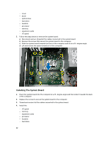
- optical drive - bezel - cover 5. Follow the procedures in After Working Inside Your Computer. System Board Components The following image displays the system board components . 1. PCI connector 2. PCIe x1 connector 3. PCIe x16 connector 4. PCIe x1 connector 5. P2 power connector 6. processor socket 7. CPU fan connector 8. memory connectors 9. P1 power connector 10. card reader module connector 11. real-time clock reset jumper 12. password reset jumper 13. front USB connector 14. SATA connectors 15. front LED connector 16. system fan connector 17. SATA connectors 18. coin-cell battery 19. front audio connector 23
-
 1
1 -
2
-
3
-
4
-
5
-
6
-
7
-
8
-
9
-
10
-
11
-
12
-
13
-
14
-
15
-
16
-
17
-
 18
18 -
 19
19 -
 20
20 -
 21
21 -
 22
22 -
 23
23 -
 24
24 -
 25
25 -
 26
26 -
 27
27 -
 28
28 -
29
-
30
-
31
-
32
-
33
-
34
-
35
-
36
-
37
-
38
-
39
-
40
-
41
 |
 |

–
optical drive
–
bezel
–
cover
5.
Follow the procedures in After Working Inside Your Computer.
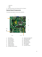
System Board Components
The following image displays the system board components .
1.
PCI connector
2.
PCIe x1 connector
3.
PCIe x16 connector
4.
PCIe x1 connector
5.
P2 power connector
6.
processor socket
7.
CPU fan connector
8.
memory connectors
9.
P1 power connector
10.
card reader module connector
11.
real-time clock reset jumper
12.
password reset jumper
13.
front USB connector
14.
SATA connectors
15.
front LED connector
16.
system fan connector
17.
SATA connectors
18.
coin-cell battery
19.
front audio connector
23