Dell Vostro 5471 Ownerss Manual - Page 24
Installing the Input output board, Power button, Removing the power button
 |
View all Dell Vostro 5471 manuals
Add to My Manuals
Save this manual to your list of manuals |
Page 24 highlights
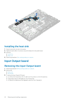
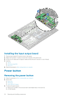
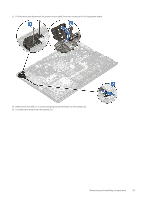
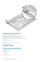
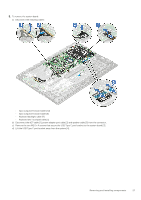
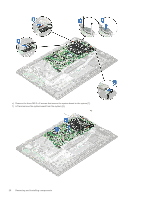
Installing the Input output board 1. Place the Input output(I/O) board to its slot in the system. 2. Replace the two M2.0 x 4 screws to secure the I/O board to the system board. 3. Connect the I/O cable and the fingerprint cable and close the latch to secure it to the I/O board. 4. Install the: a) WLAN b) solid state drive(SSD) c) base cover 5. Follow the procedure in After working inside your computer. Power button Removing the power button 1. Follow the procedure in Before working inside your computer. 2. Remove the: . a) base cover b) WLAN card c) Input output(I/O) board 3. To remove the power button: a) Remove the two M2.5 x 6 screws securing the right display hinge to the system [1]. b) Lift the hinge [2]. 24 Removing and installing components
-
 1
1 -
2
-
3
-
4
-
5
-
6
-
7
-
8
-
9
-
10
-
11
-
12
-
13
-
14
-
15
-
16
-
17
-
18
-
 19
19 -
 20
20 -
 21
21 -
 22
22 -
 23
23 -
 24
24 -
 25
25 -
 26
26 -
 27
27 -
 28
28 -
 29
29 -
30
-
31
-
32
-
33
-
34
-
35
-
36
-
37
-
38
-
39
-
40
-
41
-
42
-
43
-
44
-
45
-
46
-
47
-
48
-
49
-
50
-
51
-
52
-
53
-
54
-
55
-
56
-
57
-
58
-
59
-
60
-
61
-
62
-
63
-
64
-
65
-
66
-
67
-
68
-
69
-
70
-
71
-
72
-
73
-
74
-
75
-
76
-
77
-
78
 |
 |
