Dell Vostro 5471 Ownerss Manual - Page 39
Keyboard lattice and Keyboard, Removing the keyboard
 |
View all Dell Vostro 5471 manuals
Add to My Manuals
Save this manual to your list of manuals |
Page 39 highlights
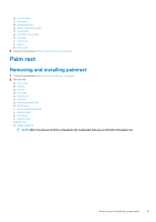
b) WLAN card c) base cover 5. Follow the procedure in After working inside your computer. Keyboard lattice and Keyboard Removing the keyboard 1. Follow the procedure in Before working inside your computer. 2. Remove the: a) base cover b) battery c) system fan d) heat sink e) solid state drive(SSD) f) WLAN card g) Input output(I/O) board h) power button i) hard drive j) system board k) display assembly 3. To remove the keyboard: a) Remove the M1.2 x 2 (33) screws that secures the keyboard to the system [1]. b) Disconnect the keyboard cable from the connector in the system [2]. c) Lift the keyboard bracket away from the system. Removing and installing components 39
-
 1
1 -
2
-
3
-
4
-
5
-
6
-
7
-
8
-
9
-
10
-
11
-
12
-
13
-
14
-
15
-
16
-
17
-
18
-
19
-
20
-
21
-
22
-
23
-
24
-
25
-
26
-
27
-
28
-
29
-
30
-
31
-
32
-
33
-
 34
34 -
 35
35 -
 36
36 -
 37
37 -
 38
38 -
 39
39 -
 40
40 -
 41
41 -
 42
42 -
 43
43 -
 44
44 -
45
-
46
-
47
-
48
-
49
-
50
-
51
-
52
-
53
-
54
-
55
-
56
-
57
-
58
-
59
-
60
-
61
-
62
-
63
-
64
-
65
-
66
-
67
-
68
-
69
-
70
-
71
-
72
-
73
-
74
-
75
-
76
-
77
-
78
 |
 |

b)
WLAN card
c)
base cover
5.
Follow the procedure in
After working inside your computer
.
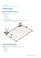
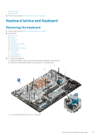
Keyboard lattice and Keyboard
Removing the keyboard
1.
Follow the procedure in
Before working inside your computer
.
2.
Remove the:
a)
base cover
b)
battery
c)
system fan
d)
heat sink
e)
solid state drive(SSD)
f)
WLAN card
g)
Input output(I/O) board
h)
power button
i)
hard drive
j)
system board
k)
display assembly
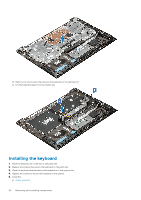
3.
To remove the keyboard:
a)
Remove the M1.2 x 2 (33) screws that secures the keyboard to the system [1].
b)
Disconnect the keyboard cable from the connector in the system [2].
c)
Lift the keyboard bracket away from the system.
Removing and installing components
39