Dell W-7024 SPR-WL2-MNT Installation Guide - Page 2
Dell W-7024 Manual
 |
View all Dell W-7024 manuals
Add to My Manuals
Save this manual to your list of manuals |
Page 2 highlights
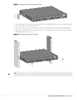
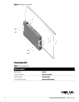
Figure 1 Attaching the Mid-Mount Brackets (W-7205) 2. Secure the brackets to the device using the eight M4 x 8 mm Phillips flat head screws for mounting bracket (four per bracket) and a suitable screwdriver. 3. If the rack requires cage nuts or clip nuts, insert them on the front rails (two per rail, aligned horizontally) 4. Mount the controller in the rack using the four M6 x 15 mm Phillips pan head screws for system rack mount and suitable screwdriver (see Figure 2). Figure 2 Mid-Mount Rack Installation (W-7205) NOTE: Leave a minimum of 10 cm (4 inches) of space on the left and right side of the controller for proper air flow and ventilation. Leave additional space in the front and the back of the controller to access network cables, LED status indicators, and power cord. 2 Dell Networking SPR-WL2-MNT | Installation Guide
-
 1
1 -
 2
2 -
 3
3 -
 4
4
 |
 |
