Dell W-Series 228 W-IAP228 Instant Access Point Installation Guide - Page 8
Connecting the Ethernet Cable, Verifying Post-Installation Connectivity
 |
View all Dell W-Series 228 manuals
Add to My Manuals
Save this manual to your list of manuals |
Page 8 highlights
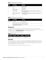
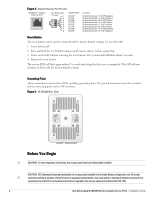
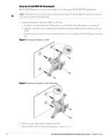
Connecting the Ethernet Cable To connect the Ethernet cable to the IAP, perform the following steps using the cable glands that ships with your IAP. WARNING: Failure to use the included Ethernet cable glands can lead to connectivity and POE issues. NOTE: The Ethernet cable is not included and must be purchased separately. Purchase a suitable UV-resistant, outdoor rated, CAT 5E or better RJ45 cable for use with the IAP. Figure 9 Installing a Cable Gland Seal Sealing Nut Clamping Ring CAT 5E or Better Cable 1. Slide the sealing nut over the cable (without the RJ45 connector attached to the end). 2. Slide the clamping ring over the cable. 3. Using a crimping tool, attach the shielded RJ45 connector to the end of the cable. 4. Remove the weatherproof cap on the Ethernet port. 5. Insert the RJ45 connector to the Ethernet port. 6. Screw the clamping ring onto the Ethernet port. 7. Screw the sealing nut onto the clamping ring. NOTE: The seal inside the clamping ring is applicable for cables with 5-8.5 mm diameter. In the cable gland kit, another seal is provided for use with the cables with 7-10 mm diameter. Verifying Post-Installation Connectivity The integrated LEDs on the IAP can be used to verify that the IAP is receiving power and initializing successfully (see Table 1 and Table 2). Refer to the Dell Networking W-Series Instant Quick Start Guide for details on verifying post-installation network connectivity. 8 Dell Networking W-IAP228 Wireless Instant Access Point | Installation Guide
-
 1
1 -
2
-
 3
3 -
 4
4 -
 5
5 -
 6
6 -
 7
7 -
 8
8 -
 9
9 -
 10
10 -
 11
11 -
 12
12 -
 13
13 -
14
-
15
-
16
 |
 |
