| Section |
Page |
| Dell™ Networking™ X1000 and X4000 Series Switches User Guide |
1 |
| Notes, Cautions, and Warnings |
2 |
| Table of Contents |
3 |
| 1 |
13 |
| Preface |
13 |
| 2 |
15 |
| Features |
15 |
| IP Version 6 (IPv6) Support |
16 |
| Head of Line Blocking Prevention |
16 |
| Back Pressure Support |
16 |
| Virtual Cable Testing (VCT) |
16 |
| Auto-Negotiation |
16 |
| MDI/MDIX Support |
17 |
| MAC Address Capacity Support |
17 |
| MAC Address Capacity Support |
17 |
| Static MAC Entries |
17 |
| Self-Learning MAC Addresses |
17 |
| Automatic Aging for MAC Addresses |
18 |
| VLAN-Aware MAC-Based Switching |
18 |
| MAC Multicast Support |
18 |
| Layer 2 Features |
18 |
| IGMP Snooping |
18 |
| MLD Snooping |
19 |
| Port and VLAN Mirroring |
19 |
| Broadcast Storm Control |
19 |
| VLAN Supported Features |
19 |
| VLAN Support |
19 |
| Port-Based Virtual LANs (VLANs) |
19 |
| Full 802.1Q VLAN Tagging Compliance |
20 |
| GVRP Support |
20 |
| Voice VLAN |
20 |
| Guest VLAN |
20 |
| Private VLAN |
21 |
| Multicast TV VLAN |
21 |
| Spanning Tree Protocol Features |
21 |
| Spanning Tree Protocol (STP) |
21 |
| Fast Link |
21 |
| IEEE 802.1w Rapid Spanning Tree |
22 |
| IEEE 802.1s Multiple Spanning Tree |
22 |
| STP BPDU Guard |
22 |
| Link Aggregation |
22 |
| Link Aggregation and LACP |
23 |
| DHCP Clients |
23 |
| Quality of Service Features |
23 |
| Class of Service 802.1p Support |
23 |
| TCP Congestion Avoidance |
23 |
| Device Management Features |
24 |
| SNMP Alarms and Trap Logs |
24 |
| SNMP Versions 1, 2, and 3 |
24 |
| Web-Based Management |
24 |
| Management IP Address Conflict Notification |
24 |
| Configuration File |
24 |
| Auto-Update of Configuration/Image File |
25 |
| TFTP (Trivial File Transfer Protocol) |
25 |
| USB File Transfer Protocol |
25 |
| Remote Monitoring |
25 |
| sFlow |
25 |
| Command Line Interface |
26 |
| SYSLOG |
26 |
| SNTP |
26 |
| Domain Name System |
26 |
| 802.1ab (LLDP-MED) |
27 |
| Security Features |
27 |
| Dot1x and MAC based Authentication |
27 |
| Locked Port Support |
28 |
| RADIUS Client |
28 |
| RADIUS Accounting |
28 |
| TACACS+ |
28 |
| Password Management |
28 |
| Access Control Lists (ACL) |
29 |
| Dynamic ACL/Dynamic Policy Assignment (DACL/DPA) |
29 |
| DHCP Snooping |
29 |
| DHCP Relay |
29 |
| ARP Inspection |
30 |
| Port Profile |
30 |
| DHCP Server |
30 |
| Protected Ports |
30 |
| Proprietary Protocol Filtering |
30 |
| UDLD |
31 |
| Static Routing |
31 |
| IPv6 Router |
31 |
| 3 |
33 |
| Hardware Description |
33 |
| Device Models |
34 |
| Device Structure |
35 |
| Managed Mode Button |
36 |
| Reset Button |
36 |
| Fans |
37 |
| LED Definitions |
37 |
| System LEDs |
37 |
| Table 3-1. |
37 |
| Port LEDs |
38 |
| Gigabit Copper Ports |
38 |
| Table 3-2. |
38 |
| SFP Ports |
39 |
| Table 3-3. |
39 |
| SFP+ Ports |
39 |
| Table 3-4. |
39 |
| Power Supplies |
39 |
| Table 3-5. |
40 |
| Table 3-6. |
40 |
| Table 3-7. |
40 |
| Table 3-8. |
41 |
| Table 3-9. |
41 |
| Table 3-10. |
41 |
| Table 3-11. |
41 |
| Table 3-12. |
41 |
| 4 |
43 |
| Using the GUI |
43 |
| Starting the Application |
44 |
| 1 Open a web browser. |
44 |
| 2 Enter the device’s IP address in the address bar and press <Enter>. The default IP address for the device is 192.168.2.1. |
44 |
| 3 When the Log In window displays, enter a user name and password. The default user name and password is admin/admin. |
44 |
| 4 Click OK. |
44 |
| Understanding the Interface |
44 |
| Dashboard |
45 |
| Saving Configurations |
45 |
| Information Buttons |
46 |
| Table 4-1. Masthead Buttons |
46 |
| Device Management Icons |
47 |
| Table 4-2. Common Icons |
47 |
| Field Definitions |
47 |
| Common GUI Features |
48 |
| Table 4-3. Common GUI Elements |
48 |
| 5 |
49 |
| Dashboard |
49 |
| Overview |
50 |
| Interfaces |
51 |
| Port Tab |
51 |
| VLAN Tab |
52 |
| LAG Tab |
52 |
| Port Profile Tab |
52 |
| Switch Information |
53 |
| Resources |
55 |
| Recent Logged Events |
57 |
| Active Alerts |
58 |
| Ports and VLANs |
59 |
| Configuration Wizards |
60 |
| 1 Click on the Ports button from the dashboard and select one or more ports to configure. |
60 |
| 2 Click Next. |
60 |
| 3 Enter a description of the port(s) in Port Description (optional). |
60 |
| 4 Click Next and enter the following: |
60 |
| 5 Click Next. |
61 |
| 6 Depending on the type of port being configured, enter the following fields: |
61 |
| 7 Click Next to view a summary of the port configuration. |
63 |
| 8 Click Apply to save the changes. |
63 |
| LAG |
63 |
| 1 Select Assign Ports to a LAG. |
63 |
| 2 Click Next. |
63 |
| 3 Select one or more ports to assign to a LAG. |
63 |
| 4 Enter the following fields: |
63 |
| 5 In the Assign Select Ports to VLAN and Port Tag Membership section, select whether ports will be Tagged or Untagged in the VLAN. This is possible for individual VLANs or All Future VLANs. |
64 |
| 6 Enter the following fields: |
64 |
| 7 After reviewing the summary, click Apply to save the LAG configuration. After apply is selected the wizard will bring up LAG Configuration option. |
64 |
| 1 Click View Current LAG Configuration. This describes the current LAG configurations: |
64 |
| 2 Select Configure LAG. |
65 |
| 3 Click Next. |
65 |
| 4 Click on the Edit icon of a LAG and enter the following fields: |
65 |
| 5 Click Next to view a summary of the port configuration. |
66 |
| 6 Click Apply to save the changes. |
66 |
| Configure VLAN |
66 |
| 1 Select Configure VLAN. |
66 |
| 2 Click Next and Add. |
66 |
| 3 Enter the following fields: |
66 |
| 4 Click OK. |
66 |
| 5 Click Next to view the VLAN. |
66 |
| 6 Click Apply to save the changes. |
66 |
| 1 Select Configure and Assign Ports to VLAN. |
66 |
| 2 Click Next. |
66 |
| 3 Click on ports to be included in VLAN. |
66 |
| 4 Enter the following fields: |
66 |
| 5 Click OK. |
66 |
| 6 Click Next to view a summary of the port configuration. |
67 |
| 7 Click Apply to save the changes. |
67 |
| Port Profile |
67 |
| 1 Click Port Profile. |
67 |
| 2 Click Next. |
67 |
| 3 Select one or more ports to assign to a port profile. |
67 |
| 4 Select Assign Port to Profile in Port Edit Mode field. |
67 |
| 5 Select one of the following profiles to assign to ports: |
67 |
| 6 Each profile requires entering various elements of VLAN information. Enter the fields according to the profile: |
67 |
| 7 Click Next to view the configuration. |
68 |
| 8 Click Apply to save the changes. |
68 |
| Initial Setup |
68 |
| 1 Click Initial Setup. |
68 |
| 2 Click Next. |
68 |
| 3 Enter the IP Address Source. Select one of the following options: |
68 |
| 4 If the IP Address Source is Static IP, enter the fields: |
69 |
| 5 Click Next. |
69 |
| 6 Enter the following fields: |
69 |
| 7 Click Next. |
69 |
| 8 Enter the following fields: |
69 |
| 9 Click Next. |
69 |
| 10 Enter the following fields: |
69 |
| 11 Click Next to view a summary of the port configuration. |
69 |
| 12 Click Apply to save the changes. |
69 |
| 6 |
71 |
| Switch Management |
71 |
| IP Addressing Overview |
71 |
| Difference Between IPv4 and IPv6 Addressing |
71 |
| IPv6 Prefixes |
72 |
| Switch Information |
72 |
| 1 Click Switch Management > Switch Information. |
72 |
| 2 Click Edit and enter the fields: |
72 |
| IPv4 Addressing |
73 |
| IPv4 Default Gateway |
74 |
| IPv4 Addressing |
74 |
| 1 Click Switch Management > IPv4 Addressing. |
74 |
| 2 To assign the IP address of the interface, on which IPv4 routing is enabled, click Edit, Add and enter the fields: |
75 |
| IPv6 Addressing |
75 |
| IPv6 Global Parameters |
76 |
| 1 Click Switch Management > IPv6 Addressing > Global Parameters. |
76 |
| 2 Click Edit and enter values for the following fields: |
76 |
| IPv6 Interface |
76 |
| 1 Click Switch Management > IPv6 Addressing > IPv6 Interface. |
76 |
| 2 Click Edit, Add and enter the fields: |
77 |
| IPv6 Address |
78 |
| 1 Click Switch Management > IPv6 Addressing > IPv6 Address. |
78 |
| 2 Click Edit. |
78 |
| 3 To enable IPv6 support on this interface, click Edit, Add and enter the following fields: |
78 |
| IPv6 Default Gateway |
79 |
| 1 Click Switch Management > IPv6 Addressing > IPv6 Default Gateway. |
79 |
| 2 To add an IPv6 default gateway, click Edit, Add, and enter the fields: |
80 |
| IPv6 Neighbors |
80 |
| 1 Click Switch Management > IPv6 Addressing > IPv6 Neighbors. |
81 |
| 2 To add a new IPv6 neighbor, click Edit, Add, and enter the fields: |
81 |
| 3 To modify or remove an IPv6 neighbor, click Edit, and enter the fields described above page. |
81 |
| File Update and Backup |
83 |
| Overview |
83 |
| System Files |
83 |
| Updating System Files |
84 |
| Update Firmware / Configuration |
84 |
| 1 Click Switch Management > File Update and Backup > Update Firmware / Configuration. |
84 |
| 2 Click Edit. |
84 |
| 3 Enter the following IP Format fields: |
85 |
| 5 Click OK to start the upload process. |
86 |
| Backup Files |
86 |
| 1 Click Switch Management > File Update and Backup > Backup Files. |
86 |
| 2 Click Edit. |
86 |
| 5 Click Apply to start the backup process. |
87 |
| Active Firmware Image |
87 |
| 1 Click Switch Management > File Update and Backup > Active Firmware Image. |
87 |
| 2 Click Edit. |
87 |
| 3 Click OK to select the image file to be used. |
88 |
| Auto-Update |
88 |
| Setup Files |
88 |
| Setup File Contents |
88 |
| Setup File Format |
89 |
| Triggering the Auto Update of Configuration/Image File Process |
91 |
| Automatic DHCP IP Address Assignment |
92 |
| Preparations for Using Auto Configuration from a TFTP Server |
94 |
| Auto Configuration (One File Read Method) |
94 |
| Auto Configuration (Multi File Read Method) |
95 |
| Preparations for Firmware Image Download from TFTP |
96 |
| Auto Update of Configuration/Image File |
97 |
| 1 Click Switch Management > File Update and Backup > Auto Update of Configuration/Image File. |
97 |
| 2 Modify the auto-update configuration parameters as required: |
97 |
| Restore Factory Defaults |
98 |
| 1 Click Switch Management > File Update and Backup > Restore Factory Defaults. |
98 |
| 2 Click Edit. |
98 |
| 3 Select Restore Switch Configuration to replace the current configuration settings by the factory configuration default settings. |
98 |
| Domain Name System (DNS) |
98 |
| DNS Settings |
98 |
| 1 Click Switch Management > DNS Settings (DNS) > DNS Settings. |
98 |
| 2 Click Edit, Settings Icon () to set the global DNS properties. |
98 |
| 3 Enter the following fields: |
98 |
| 4 Click OK. |
98 |
| 5 To activate one of the currently-defined DNS servers, enable Active Server. |
98 |
| Host Name Mapping |
99 |
| 1 Click Switch Management > Domain Name (DNS) > Host Name Mapping. |
99 |
| 2 Click Add to add a new host name. Up to four IP addresses can be added. |
99 |
| Time Synchronization |
100 |
| Clock Source |
101 |
| 1 Click Switch Management > Time Synchronization > Clock Source. |
101 |
| 2 Select the Clock Source. The possible options are: |
101 |
| Local Time Settings |
101 |
| 1 Click Switch Management > Time Synchronization > Local Time Settings. |
101 |
| 2 Enter the following local settings: |
101 |
| System Time from an SNTP Server |
103 |
| Overview |
103 |
| SNTP Global Settings |
106 |
| 1 Click Switch Management > Time Synchronization > SNTP Global Settings. |
107 |
| 2 Enter the fields: |
107 |
| SNTP Authentication |
107 |
| 1 Click Switch Management > Time Synchronization > SNTP Authentication. |
107 |
| 2 Click Edit, Settings Icon () to enable/disable SNTP Authentication. This enables/disables authenticating SNTP sessions between the device and an SNTP server. |
107 |
| 3 Click OK. |
107 |
| SNTP Servers |
108 |
| 1 Click Switch Management > Time Synchronization > SNTP Servers. |
108 |
| SNTP Interface Settings |
109 |
| 1 Click Switch Management > Time Synchronization > SNTP Interface Settings. |
109 |
| 2 To add an interface that can receive SNTP server updates, click Edit, Add. |
110 |
| 3 Enter the following fields: |
110 |
| Management Security |
110 |
| Global Password Management |
110 |
| 1 Click Switch Management > Management Security > Global Password Management. |
111 |
| Line Password for CLI |
112 |
| 1 Click Switch Management > Management Security > Line Password for CLI. |
112 |
| Enable Password for CLI |
112 |
| 1 Click Switch Management > Management Security > Enable Password for CLI. |
113 |
| 1 Click Edit to enter the fields: |
113 |
| Active Users |
113 |
| Local User Database |
114 |
| 1 Click Switch Management > Management Security > Local User Database. |
114 |
| Access Profiles and Rules Configuration |
114 |
| Access Profiles and Rules |
115 |
| 1 Click Switch Management > Management Security > Access Profiles and Rules. |
116 |
| 2 Click Add and enter the fields: |
116 |
| 1 Click Switch Management > Management Security > Access Profiles and Rules. |
117 |
| 2 To activate an access profile, select it in the Active Access Profile field. |
117 |
| 3 Click Edit, Settings Icon (). |
117 |
| 4 Select one of the following options for Access Profile Name: |
117 |
| 5 Click OK. |
118 |
| Authentication Profiles |
118 |
| 1 Click Switch Management > Management Security > Authentication Profiles. |
118 |
| 2 Click Edit, Add to add a new authentication profile, and enter the fields: |
119 |
| Select Authentication |
119 |
| 1 Click Switch Management > Management Security > Select Authentication. |
119 |
| 2 For the Console, Telnet and Secure Telnet (SSH) types of users, select either the default authentication profile or one of the previously-defined authentication profiles. |
119 |
| 3 For Secure HTTP and HTTP types of users, select one or all of the Optional Methods and click the right-arrow to move them to the Selected Methods. The options are: |
120 |
| TACACS+ |
120 |
| 1 Click Switch Management > Management Security > TACACS+. |
120 |
| 2 To set the global parameters, click Edit, Settings Icon () and enter the following fields: |
120 |
| 3 Click OK. |
121 |
| 4 To add a TACACS+ server, click Edit, Add and enter the following fields: |
121 |
| RADIUS |
121 |
| 1 Click Switch Management > Management Security > RADIUS. |
122 |
| 2 To set the global parameters, click Edit, Settings Icon () and enter the following fields: |
122 |
| 3 Click OK. |
122 |
| 4 To add a RADIUS server, click Edit, Add, and enter the fields: |
122 |
| 7 |
125 |
| Logs and Alerts |
125 |
| Overview |
125 |
| Logs |
126 |
| 1 Click Logs and Alerts > Logs. |
126 |
| 2 Click Edit, Settings Icon (). |
126 |
| 3 Enable/disable logging in the following fields: |
126 |
| 4 To select the destination of logging messages, according to their severity levels, check the minimum severity level that will be associated with the console log, RAM log and Log file (Flash memory). When a severity level is selected, all severity l... |
127 |
| Login History |
127 |
| 1 Click Logs and Alerts > Login History. |
127 |
| 2 Click Edit, Settings Icon (). |
127 |
| 3 Enable/disable Login History to File to record login history. |
127 |
| Remote Log Servers |
127 |
| 1 Click Logs and Alerts > Remote Log Servers. |
127 |
| 2 Click Edit, Add, and enter the fields: |
127 |
| 8 |
129 |
| Statistics and Diagnostics |
129 |
| Monitoring |
129 |
| Statistics |
129 |
| 1 Click Statistics and Diagnosis > Monitoring (RMON). |
129 |
| 2 Click Statistics. |
129 |
| 3 Select a port or LAG. |
129 |
| 4 Select one of the Refresh Rate options to specify how frequently the statistics should be refreshed. |
131 |
| 5 Select Reset All Counters to clear the counters. |
131 |
| CPU Utilization |
131 |
| 1 Click Statistics and Diagnosis > Monitoring (RMON). |
131 |
| 2 Click CPU Utilization. |
131 |
| 3 Select one of the Refresh Rate options to specify how frequently the statistics should be refreshed. |
131 |
| 4 Click Reset Counters to clear the counters. |
131 |
| History Control |
131 |
| 1 Click Statistics and Diagnosis > Monitoring (RMON). |
131 |
| 2 Click History Control. |
131 |
| 3 To add a new entry, click Add. The New History Entry number, which uniquely identifies the sample, is displayed. |
132 |
| 4 Enter the fields for the entry: |
132 |
| History Table |
132 |
| 1 Click Statistics and Diagnosis > Monitoring (RMON). |
132 |
| 2 Click History Table. |
132 |
| 3 Select a History Entry number in the View By filter. |
132 |
| Threshold and Events |
133 |
| 1 Click Statistics and Diagnosis > Monitoring (RMON). |
133 |
| 2 Click Threshold and Events. |
133 |
| 3 Click Add. |
133 |
| 4 Enter the fields: |
133 |
| Configure an Event |
134 |
| 1 Click Statistics and Diagnosis > Monitoring. |
134 |
| 2 Click Threshold and Events. |
134 |
| 3 Click Configure Events Controls, Add. |
135 |
| 4 Enter the following fields: |
135 |
| Statistics |
135 |
| Interface Counters |
135 |
| 1 Click Statistics and Diagnosis > Statistics. |
135 |
| 2 Click Interface Counters. |
135 |
| Denied ACEs Counters |
136 |
| 1 Click Statistics and Diagnosis > Statistics. |
136 |
| 2 Click Denied ACEs Counters. |
136 |
| 3 Select either Ports or LAGs in View By. |
136 |
| 4 To clear the counters, click Reset Counter. |
136 |
| EAP Statistics |
137 |
| 1 Click Statistics and Diagnosis > Statistics. |
137 |
| 2 Click EAP Statistics. |
137 |
| Etherlike Statistics |
138 |
| 1 Click Statistics and Diagnosis > Statistics. |
138 |
| 2 Click Etherlike Statistics. |
138 |
| 3 Select Ports or LAG in View By. |
138 |
| 4 Select one of the Refresh Rate options to clears the statistics for the selected interface. |
138 |
| GVRP Statistics |
138 |
| 1 Click Statistics and Diagnosis > Statistics. |
138 |
| 2 Click GVRP Statistics. |
138 |
| 3 Select Ports or LAG in View By. |
138 |
| A |
139 |
| 4 Select one of the Refresh Rate options to specify how frequently the statistics should be refreshed. |
139 |
| Utilization Summary |
139 |
| 1 Click Statistics and Diagnosis > Statistics. |
140 |
| 2 Click CPU Utilization. |
140 |
| 3 Select Ports or LAG in View By. |
140 |
| 4 Select the Refresh Rate to specify how frequently the statistics should be refreshed. |
140 |
| Diagnostics |
140 |
| Integrated Cable Test |
140 |
| 1 Click Statistics and Diagnosis > Diagnostics. |
141 |
| 2 Click Integrated Cable Test. |
141 |
| 3 Ensure that both ends of the copper cable are connected, one end to tested port and one end to device. |
141 |
| 4 Click Test for the port to be tested. The copper cable and Approximate Cable Length tests are performed, and the following test results are displayed: |
141 |
| Optical Transceiver Diagnostics |
141 |
| 1 Click Statistics and Diagnosis > Diagnostics. |
142 |
| 2 Click Optical Transceiver Diagnostics. |
142 |
| Identify |
142 |
| 1 Click Statistics and Diagnosis > Diagnostics. |
142 |
| 2 Click Identify. |
142 |
| 3 Select Identify Switch to light the Identity LED. |
142 |
| 4 Enter the Identify Switch LED Timeout. This determines how long the Identify switch will stay lit. |
142 |
| 9 |
143 |
| Network Administration: VLAN |
143 |
| VLAN Overview |
143 |
| Frame Flow |
144 |
| Figure 9-1. Frame Flow Through a VLAN |
144 |
| 1 If the frame contains a VLAN tag, that tag is used, otherwise the frame is classified by the port's default VLAN (PVID), if it is defined. |
144 |
| 2 After classification, the frame may pass (if enabled) through ingress filtering, where the frame is dropped if the frame's VLAN ID is not one of the VLANs to which the ingress port belongs. |
144 |
| 3 A forwarding decision is made, as a function of the VLAN ID and the destination MAC address. |
144 |
| 4 The egress rules define whether the frame is to be sent as tagged or untagged. |
144 |
| Special-case VLANs |
144 |
| QinQ Tagging |
145 |
| Port Modes |
145 |
| Acceptable Frame Type |
147 |
| Standard VLAN |
147 |
| VLAN Membership |
147 |
| 1 Click Network Administration > VLAN >Standard VLAN > VLAN Membership. |
147 |
| 2 Click Edit and enter the fields: |
148 |
| VLAN Port Settings |
148 |
| 1 Click Network Administration > VLAN >Standard VLAN > VLAN Port Settings. |
148 |
| 2 Click Edit. |
148 |
| 3 Select a port, click its Edit icon and enter the fields: |
148 |
| A |
150 |
| Protocol Group |
150 |
| Defining Protocol Groups |
152 |
| 1 Define a protocol group by assigning one or more protocols to the group and giving it a protocol-group ID (any integer), using the Protocol Group page. |
152 |
| 2 Associate the group with a desired VLAN classification, per port, using the Protocol Port page. |
152 |
| 1 Click Network Administration > VLAN > Standard VLAN >Protocol Group. |
152 |
| 2 Click Edit, Add and enter the fields: |
152 |
| Protocol Port |
152 |
| 1 Click Network Administration > VLAN > Standard VLAN > Protocol Port. |
152 |
| 2 Click Edit, Add, and enter the fields: |
152 |
| GVRP Parameters |
153 |
| 1 Click Network Administration > VLAN > Standard VLAN > GVRP Parameters. |
153 |
| 2 Click Edit. |
153 |
| 3 Click the Settings Icon () and enable the GVRP Global Status. |
153 |
| 4 Click OK. |
153 |
| 5 Select either Ports or LAGs to view that type of interface in the page. |
153 |
| 6 Select a port, click its Edit icon and enter the fields: |
153 |
| GARP Timers |
154 |
| 1 Click Network Administration > VLAN > Standard VLAN > GARP Timers. |
154 |
| 2 Select either Ports or LAGs to view that type of interface in the page. |
154 |
| 3 Click Edit. |
154 |
| 4 Select a port, click its Edit icon and enter the fields: |
154 |
| Private VLAN |
155 |
| 1 Click Network Administration > VLAN > Standard VLAN > Private VLAN. |
155 |
| 2 To query by Associated Primary VLAN ID, enter a VLAN ID, and click Query. The associated VLANs are displayed. |
155 |
| 3 To define a private VLAN, click Edit, Assign and enter the fields: |
155 |
| 4 To assign ports to the private VLAN, click Edit, Membership. |
156 |
| 5 Select a Primary VLAN ID. |
156 |
| 6 Select the ports to be assigned to each VLAN, and assign each port/LAG a port type. The possible options are: |
156 |
| Voice VLAN |
156 |
| Overview |
156 |
| Properties |
157 |
| 1 Click Network Administration > VLAN > Voice VLAN > Properties. |
157 |
| 2 Click Edit and enter the fields: |
157 |
| Port Settings |
158 |
| 1 Click Network Administration > VLAN > Voice VLAN > Port Setting. |
158 |
| 2 Select an interface, click its Edit icon and enter the fields: |
158 |
| OUI |
159 |
| 1 Click Network Administration > VLAN > Voice VLAN > OUI. |
159 |
| 2 Click Edit, Add, and enter the fields: |
159 |
| 10 |
161 |
| Network Administration: Port Settings |
161 |
| Ports |
161 |
| Overview |
161 |
| Auto-Negotiation |
162 |
| MDI/MDIX |
162 |
| Flow Control |
163 |
| Back Pressure |
163 |
| Port Default Settings |
163 |
| Table 10-1. Port Default Settings |
163 |
| Jumbo Frames |
164 |
| 1 Click Network Administration > Ports Settings > Jumbo Frames. |
164 |
| 2 To enable/disable jumbo frames, click Edit. |
164 |
| Protected Ports |
164 |
| Protected Port Restrictions |
165 |
| Configuration of Protected Ports |
165 |
| 1 Click Network Administration > Ports Settings > Protected Ports. |
165 |
| 2 Click Edit. |
165 |
| 3 Select the interface and click its Edit icon. |
165 |
| 4 Enter values for the following fields: |
165 |
| Port Profile |
165 |
| 1 Click Network Administration > Ports Settings > Port Profile. |
166 |
| 2 To assign a profile to an interface, click Edit. |
166 |
| 3 Select an interface and click its Edit icon. |
166 |
| 4 Select an Assigned Profile to assign to the interface. The Profile Description is displayed. The following options are available: |
166 |
| 5 Each profile requires entering various elements of VLAN information. Enter the fields according to the profile: |
166 |
| Port Configuration |
168 |
| 1 Click Network Administration > Ports Settings > Ports > Port Configuration. |
168 |
| 2 To modify the port settings, click Edit and select a port. |
168 |
| 3 Click the Edit icon of the port and enter the following fields: |
168 |
| Port and VLAN Mirrorings |
171 |
| Destination Port Restrictions |
171 |
| Source Port Restrictions |
172 |
| Port and VLAN Mirroring |
172 |
| 1 Click Network Administration > Ports Settings > Port and VLAN Mirroring. |
172 |
| 2 Select the Destination Interface. |
173 |
| 3 To add an interface to be mirrored, click Edit, Add, and enter the fields: |
173 |
| Address Tables |
173 |
| Overview |
173 |
| Static Address Table |
173 |
| 1 Click Network Administration > Port Settings > Address Tables > Static Address Table. |
174 |
| 2 To add a static address, click Edit, Add. |
174 |
| 3 Enter the following fields: |
174 |
| Dynamic Address Table |
174 |
| 1 Click Network Administration > Port Settings > Dynamic Address Table. |
175 |
| 2 Click Edit, Settings Icon (). |
175 |
| 3 Enter Address Aging (sec). The aging time is a value between the user- configured value and twice that value minus 1. For example, if you entered 300 seconds, the aging time is between 300 and 599 seconds. |
175 |
| 4 Click OK. |
175 |
| 5 To clear the table, check Clear Table. |
175 |
| 6 To display a subset of the addresses in a particular order, click the Filter icon and enter the following query criteria: |
175 |
| 7 Click Query to see the results. |
175 |
| UDLD |
175 |
| Overview |
175 |
| UDLD States and Modes |
176 |
| How UDLD Works |
177 |
| UDLD Not Supported or is Disabled on a Neighbor |
178 |
| Inconsistent UDLD Mode in Local and Neighboring Device |
178 |
| Reactivating a Shutdown Port |
178 |
| Usage Guidelines |
179 |
| Dependencies On Other Features |
179 |
| Default Settings and Configuration |
179 |
| Common UDLD Tasks |
180 |
| Workflow1: To globally enable UDLD on fiber ports, perform the following steps: |
180 |
| Workflow2: To change the UDLD configuration of a fiber port or to enable UDLD on a copper port, perform the following steps: |
180 |
| 1 Open the UDLD Global Settings page. |
180 |
| 2 Click Apply. |
180 |
| UDLD Global Settings |
180 |
| 1 Click Network Administration > Port Settings > Unidirectional Link Detection (UDLD) > UDLD Global Settings. |
181 |
| 2 Click Edit and enter the following fields: |
181 |
| UDLD Interface Settings |
181 |
| 1 Click Network Administration > Port Settings > Unidirectional Link Detection (UDLD) > UDLD Interface Settings. |
181 |
| 2 To modify the UDLD state for a specific port, click its Edit icon and select the port. |
182 |
| 3 Modify the value of the UDLD state. If you select Default, the port receives the value of the Fiber Port UDLD Default State in the UDLD Global Settings page. |
182 |
| UDLD Neighbors |
182 |
| 1 Click Network Administration > Port Settings > UDLD Neighbors. |
182 |
| 11 |
185 |
| Network Administration: Spanning Tree and LAG |
185 |
| Spanning Tree |
185 |
| Spanning Tree Overview |
185 |
| Global Settings |
187 |
| 1 Click Network Administration > Spanning Tree and LAG > Spanning Tree > Global Settings. |
187 |
| 2 Click Edit and enter the fields: |
187 |
| STP Port Settings |
189 |
| 1 Click Network Administration > Spanning Tree and LAG > Spanning Tree > STP Port Settings. |
189 |
| 2 Click Edit. |
189 |
| 3 Select a port, click its Edit icon and enter the fields: |
189 |
| Rapid Spanning Tree |
191 |
| 1 Click Network Administration > Spanning Tree and LAG > Spanning Tree > Rapid Spanning Tree. |
191 |
| 2 Select either Ports or LAGs from the View By dropdown menu. |
191 |
| 3 Click Edit, select an interface, click its Edit icon and enter the fields: |
191 |
| MSTP Properties |
193 |
| 1 Click Network Administration > Spanning Tree and LAG > Spanning Tree > MSTP Properties. |
193 |
| 2 Click Edit and enter the following fields: |
193 |
| VLAN to MSTP Instance |
193 |
| 1 Click Network Administration > Spanning Tree and LAG > Spanning Tree > VLAN to MSTP Instance. |
193 |
| 2 Click Edit. |
193 |
| 3 Select the MSTP instance and click its Edit icon. |
193 |
| 4 Enter the fields: |
193 |
| MSTP Instance Settings |
194 |
| 1 Click Network Administration > Spanning Tree and LAG > MSTP Instance Settings. |
194 |
| 2 Select an Instance ID. |
194 |
| 3 Enter the Bridge Priority (0-61440) of this bridge for the selected MSTP instance. |
194 |
| 4 The following fields are displayed: |
194 |
| MSTP Interface Settings |
194 |
| 1 Click Network Administration > Spanning Tree and LAG > Spanning Tree > MSTP Interface Settings. |
194 |
| 2 Click Edit. |
194 |
| 3 Select an instance, and enter the fields: |
194 |
| Link Aggregation (LAG) |
196 |
| Overview |
196 |
| LAG Membership |
197 |
| 1 Click Network Administration > Spanning Tree and LAG > Link Aggregation (LAG) > LAG Membership. |
197 |
| 2 Click Edit. |
197 |
| 3 Select a LAG. |
197 |
| 4 Select whether it is a Standard (user-defined LAG) or an LACP-defined LAG. |
198 |
| 5 Click on the ports that will comprise the LAG. |
198 |
| LAG Configuration |
198 |
| 1 Click Network Administration > Spanning Tree and LAG > Link Aggregation (LAG) > LAG Configuration. |
198 |
| 2 Click Edit. |
198 |
| 3 Select the LAG, click its Edit icon and enter the fields: |
198 |
| LACP Parameters |
199 |
| 1 Click Network Administration > Spanning Tree and LAG > Link Aggregation (LAG) > LACP Parameters. |
200 |
| 2 Click Edit, Settings Icon () and enter the global LACP System Priority value that determines which candidate ports will become members of the LAG. |
200 |
| 3 Click OK. |
200 |
| 4 To modify LACP parameters for a particular port, click Edit, select a port and enter the following fields: |
200 |
| VLAN LAG Membership |
200 |
| 1 Click Network Administration > Spanning Tree and LAG > Link Aggregation (LAG) > VLAN LAG Membership. |
200 |
| 2 Select a VLAN and click Edit. |
200 |
| VLAN LAG Settings |
201 |
| 1 Click Network Administration > Spanning Tree and LAG > Link Aggregation (LAG) > VLAN LAG Settings. |
201 |
| 2 Click Edit, select a LAG, click its Edit icon and enter the fields: |
201 |
| STP LAG Settings |
203 |
| 1 Click Network Administration > Spanning Tree and LAG > Link Aggregation (LAG) > STP LAG Settings. |
203 |
| 2 Click Edit, select a LAG and click its Edit icon. |
203 |
| 3 Enter the fields. |
203 |
| 12 |
207 |
| Network Administration: Link Layer Discovery Protocol (LLDP) |
207 |
| Overview |
207 |
| LLDP Properties |
208 |
| 1 Click Network Administration > Link Layer Discovery Protocol (LLDP) > LLDP Properties. |
208 |
| 2 Click Edit and enter the fields: |
208 |
| LLDP Port Settings |
209 |
| 1 Click Network Administration > Link Layer Discovery Protocol (LLDP) > LLDP Port Settings. |
209 |
| 2 Click Edit and click the Edit icon of the port to be configured. |
209 |
| 3 Select the transmission type on which LLDP is to be configured in the State field. The possible options are: |
209 |
| 4 Move the optional TLVs that the switch should advertise from the Available TLV list to the Optional TLV list. The TLVs advertise the following: |
209 |
| 5 Enter the Management IP Address that is advertised from the interface. Check Use Default to use the default Management IP address. |
210 |
| MED Network Policy |
210 |
| 1 Click Network Administration > Link Layer Discovery Protocol (LLDP) > MED Network Policy. |
210 |
| 2 Click Edit, Add, and enter the fields: |
211 |
| MED Port Settings |
211 |
| 1 Click Network Administration > Link Layer Discovery Protocol (LLDP) > MED Port Settings. |
211 |
| 2 The following fields are displayed for each port: |
211 |
| 3 To modify network policies on a port, click Edit. |
211 |
| 4 Select the port to be configured, and enter the fields for the port: |
211 |
| 5 To view MED details for a port, return to the main page and click the Detail icon of the selected port. |
212 |
| Neighbors Information |
213 |
| 1 Click Network Administration > Link Layer Discovery Protocol (LLDP) > Neighbors Information. |
213 |
| 2 Click Clear Neighbors Table to delete all the entries or select Remove to delete a specific port entry. |
214 |
| 3 Click the Details button of a port. |
214 |
| 13 |
215 |
| Network Administration: Route Settings |
215 |
| System Routing Mode |
215 |
| System Routing Mode |
215 |
| 1 Click Network Administration > Route Settings > IPv4 Route Settings > System Routing Mode. |
215 |
| 2 Click Edit. |
215 |
| 3 Select either Layer 2 or Layer 2+ Static Routing. |
215 |
| IPv4 Route Settings |
215 |
| IPv4 Routes Table |
216 |
| For devices in Layer 2 + Static Routing system mode |
216 |
| 1 Click Network Administration > Route Settings > IPv4 Route Settings > IPv4 Routes Tables. |
216 |
| 2 Click Edit, Add and enter the required fields (these are described above). |
217 |
| For devices that always support Layer 2 + Static Routing |
217 |
| 1 Click Network Administration > Route Settings > IPv4 Route Settings > IPv4 Routes Tables. |
217 |
| 2 Click Add and enter the required fields (that are described above). |
217 |
| IPv4 Default Metric for Default Routes for Layer 2 + Static Routing |
217 |
| ARP Table |
218 |
| 1 Click Network Administration > Route Settings > IPv4 Route Settings > ARP Table. |
218 |
| 2 Click Edit, Settings Icon () and enter the parameters: |
218 |
| 3 To add a mapping, click Add, and enter the fields: |
218 |
| 4 To change the status of a mapping from static to dynamic or vice versa, click Edit from the main page. |
219 |
| 5 Select an interface and enter the field: |
219 |
| UDP Relay |
219 |
| 1 Click Network Administration > Route Settings > IPv4 Route Settings > UDP Relay. |
219 |
| 2 To add a UDP relay, click Edit, Add, and enter the fields: |
219 |
| IPv6 Route Settings |
220 |
| IPv6 Routes Table |
220 |
| 1 Click Network Administration > Route Settings > IPv6 Routes Settings > IPv6 Routes Table. |
220 |
| 2 Click Edit, Add and enter the fields as described above for the new route. |
221 |
| ISATAP Tunnel |
221 |
| 1 Click Network Administration > Route Settings > IPv6 Routes Settings > ISATAP Tunnel. |
222 |
| 2 Click Edit and enter the fields: |
222 |
| Router Advertisement |
223 |
| 1 Click Network Administration > Route Settings > IPv6 Routes Settings > Router Advertisement. |
223 |
| 2 To configure an interface listed in the Router Advertisement Table, click Edit. |
223 |
| 3 Select an interface and enter the following fields: |
223 |
| IPv6 Prefixes |
225 |
| 1 Click Network Administration > Route Settings > IPv6 Routes Settings > IPv6 Prefixes. |
225 |
| 2 To add an interface, click Edit, Add. |
225 |
| 3 Select the required IPv6 Interface on which a prefix is to be added. |
225 |
| 4 Enter the following fields: |
225 |
| 14 |
227 |
| Network Administration: Quality of Service |
227 |
| Overview |
227 |
| Global Settings |
228 |
| QoS Properties |
228 |
| 1 Click Network Administration > Quality of Service > Global Settings > QoS Properties. |
228 |
| 2 To modify the CoS value for an interface, click Edit. |
228 |
| 3 Select a port, click its Edit icon and enter the fields: |
228 |
| Queue Scheduling |
228 |
| Traffic Limitation Methods |
228 |
| Combination of WRR and Strict Priority |
229 |
| 1 Click Network Administration > Quality of Service > Global Settings > Queue Scheduling. |
229 |
| 2 Click Enter and enter the following parameters for each queue: |
229 |
| CoS to Queue |
230 |
| Table 14-1. |
230 |
| 1 Click Network Administration > Quality of Service > Global Settings > CoS to Queue. |
230 |
| 2 Click Edit and enter the fields: |
231 |
| DSCP to Queue |
231 |
| Table 14-2. |
231 |
| 1 Click Network Administration > Quality of Service > Global Settings > DSCP to Queue. |
231 |
| 2 Click Edit and enter the fields: |
232 |
| Bandwidth Management |
232 |
| 1 Click Network Administration > Quality of Service > Global Settings > Bandwidth Management. |
232 |
| 2 Select either Ports or LAGs in the top drop-down menu to select the type of interfaces to be displayed. |
232 |
| 3 To set interface parameters, click Edit. |
232 |
| 4 Select an interface, click its Edit icon and enter the fields: |
232 |
| TCP Congestion Avoidance |
233 |
| 1 Click Network Administration > Quality of Service > Global Settings > TCP Congestion Avoidance. |
233 |
| 2 Click Edit and select either Enabled/Disabled to TCP Congestion Avoidance to enable/disable the algorithm. |
233 |
| QoS Mapping |
233 |
| Overview |
234 |
| Workflow to Perform QoS Mapping |
235 |
| 1 If external DSCP values are different from those used on incoming packets, map the external values to internal values in the DSCP Mapping page. |
235 |
| 2 Create ACLs, as described in \ |
235 |
| 3 When ACLs are defined, create class maps and associate the ACLs with them in the \ |
235 |
| 4 Create a policy map in the \ |
235 |
| a Single Policer — Create a policy that associates a class map with a single policer in the \ |
235 |
| b Aggregate Policer — Create a QoS action for each flow. This action sends all matching frames to the same policer (aggregate policer), defined in the \ |
235 |
| 5 Bind the policy to an interface in the \ |
235 |
| DSCP Mapping |
236 |
| 1 Click Network Administration > QoS Mapping > DSCP Mapping. |
236 |
| 2 If the Exceed Action is Out-of-Profile DSCP (in the \ |
236 |
| Class Mapping |
236 |
| 1 Click Network Administration > QoS Mapping > Class Mapping. |
237 |
| 2 To add a class map, click Edit, Add. |
237 |
| 3 Enter the parameters. |
237 |
| Policers |
237 |
| Aggregate Policer |
238 |
| 1 Click Quality of Service > QoS Mapping > Aggregate Policer. |
239 |
| 2 To add an aggregate policer, click Edit, Add, and enter the fields. |
239 |
| Policy Table |
239 |
| 1 Create a policy in the Policy Table pages |
239 |
| 2 Configure the policy in the Policy Class Maps pages. Here the policy class can be designated as containing a single policer, or it can be designated as containing Aggregate policers. |
239 |
| 1 Click Quality of Service > QoS Mapping > Policy Table. |
240 |
| 2 To create a policy, click Edit, Add. |
240 |
| 3 Enter the name of the new policy in the Policy Name field. |
240 |
| 4 Add class maps to the new policy in the Policy Class Maps page. |
240 |
| Policy Class Maps |
240 |
| 1 Click Quality of Service > QoS Mapping > Policy Class Maps. |
240 |
| 2 Select a policy in the Policy Name field. The class maps in that policy are displayed. |
240 |
| 3 To add a class map, click Edit. |
240 |
| 4 Select a Class Map from the View By menu, click Add and enter the parameters. |
240 |
| Policy Binding |
242 |
| 1 Click Network Administration > QoS Mapping > Policy Binding. |
242 |
| 2 To bind a policy to an interface, click Add. |
242 |
| 3 Select the interface type of the interface assigned to the policy (Port or LAG). |
242 |
| 4 Select the interface assigned to the policy. |
242 |
| 5 Select the Policy Name to be activated on the interface. |
242 |
| QoS Statistics |
242 |
| Policer Statistics |
242 |
| 1 Click Network Administration > Quality of Service > QoS Statistics > Policer Statistics. |
243 |
| 2 Click Edit, Add to add a new counter that applies to another policy-class map. |
243 |
| 3 Enter the fields: |
243 |
| Aggregated Policer |
243 |
| 1 Click Network Administration > Quality of Service > QoS Statistics > Aggregate Policer. |
243 |
| 2 To add a new counter that applies to another aggregate policer, click Edit, Add. |
243 |
| 3 Select an aggregate policer in the Aggregate Policer Name field. |
244 |
| Queues Statistics |
244 |
| 1 Click Network Administration > Quality of Service > QoS Statistics > Queues Statistics. |
244 |
| 2 To add a new counter, click Add, and enter the fields: |
244 |
| 15 |
245 |
| Network Administration: Security |
245 |
| Dot1x Authentications |
245 |
| Port-Based Authentication Overview |
245 |
| Dot1x Overview |
246 |
| Dynamic VLAN Assignment (DVA) |
247 |
| Dynamic Policy/ACL Assignment |
247 |
| Authentication Methods |
248 |
| Unauthenticated VLAN and Guest VLANs |
248 |
| Port-Based Authentication Global |
249 |
| 1 Click Network Administration > Security > Dot1 Authentications > Port Based Authentication - Global. |
249 |
| 2 Enter the following fields: |
249 |
| Port-Based Authentication Interface Settings |
250 |
| 1 Click Network Administration > Security > Dot1 Authentications > Port Based Authentication - Interface Settings. |
250 |
| 2 Click Edit. |
250 |
| 3 Select a port for which the authentication parameters apply in the Interface drop-down list. |
250 |
| 4 Enter the parameters: |
250 |
| a Set authentication type to 802.1x Only. |
251 |
| b Enable Periodic Reauthentication. |
251 |
| c Save the configuration. |
251 |
| d Re-enter the 802.1x interface settings and change the authentication type to MAC Only or 802.1x & MAC. |
251 |
| e Save the configuration. |
251 |
| . |
251 |
| Host Authentication |
253 |
| 1 Click Network Administration > Security > Dot1 Authentications > Host Authentication. |
253 |
| 2 Click Edit. |
254 |
| 3 Select the port to which you want to apply the authentication mode and click its Edit icon. |
254 |
| 4 Enter the fields: |
254 |
| Port Authentication Users |
254 |
| 1 Click Network Administration > Security > Dot1 Authentications > Port Authentication Users. |
255 |
| Storm Control Configuration |
255 |
| Storm Control |
256 |
| 1 Click Network Administration > Security > Storm Control. |
256 |
| 2 To configure Storm Control on a port, click Edit. |
256 |
| 3 Select a port from the Port drop-down list, click its Edit button and enter the following fields: |
256 |
| Port Security |
256 |
| Port Security |
257 |
| 1 Click Network Administration > Security > Port Security. |
257 |
| 2 Select the type of interface Ports or LAGs. |
257 |
| 3 Select an interface and click its Edit icon. |
257 |
| 4 The following fields are displayed: |
257 |
| 5 When the port is unlocked (Set Port = Unlocked), enter the following fields: |
257 |
| 6 Click OK. |
257 |
| 7 Click the Edit icon for the port again. |
257 |
| 8 Set Set Port to Locked. |
258 |
| 9 Enter the following fields: |
258 |
| 10 Click OK. The feature is operational on the interface. |
258 |
| Dynamic ARP Inspection (DAI) |
258 |
| Overview |
258 |
| Global Settings |
259 |
| 1 Click Network Administration > Security > Dynamic ARP Inspection (DAI) > Global Settings. |
259 |
| 2 Enter the fields: |
259 |
| DAI List |
260 |
| 1 Click Network Administration > Security > Dynamic ARP Inspection (DAI) > DAI List. |
260 |
| 2 To create a new list and enter the first address pair in it, click Edit, Add, and enter the fields: |
260 |
| DAI Entries |
260 |
| 1 Click Network Administration > Security > Dynamic ARP Inspection (DAI) > DAI Entries. |
260 |
| 2 To add a new address pair to a list, click Edit, Add and select the list. |
260 |
| 3 Enter the fields: |
260 |
| DAI VLAN Settings |
261 |
| 1 Click Network Administration > Security > Dynamic ARP Inspection (DAI) > DAI VLAN Settings. |
261 |
| 2 To designate a VLAN to be associated with an ARP inspection list, click Edit, Add and enter the VLAN ID. |
261 |
| 3 To add a list to the VLAN, return to the main page, select the Edit icon associated with the VLAN and select a List Name to be associated with the VLAN. |
261 |
| Trusted Interfaces |
261 |
| 1 Click Network Administration > Security > Dynamic ARP Inspection (DAI) > Trusted Interfaces. |
261 |
| 2 In the View By menu, select whether to display ports or LAGs. |
261 |
| 3 To modify the status of an interface, click Edit. |
261 |
| 4 Select the interface and click its Edit icon. |
261 |
| 5 Enable/disable its Trust status, which is the DHCP Snooping Trust mode. |
261 |
| ACL and ACE |
261 |
| Overview |
262 |
| MAC-Based ACLs |
262 |
| 1 Click Network Administration > Security > ACL and ACE > MAC Based ACL. |
263 |
| 2 To add a new ACL, click Edit, Add and enter the name of the new ACL. |
263 |
| MAC-Based ACEs |
263 |
| 1 Click Network Administration > Security > ACL and ACE > MAC Based ACE. |
263 |
| 2 To add a rule, click Edit, Add. |
263 |
| 3 Select the ACL for which a rule is being created. |
263 |
| 4 Enter the fields: |
263 |
| IPv4-Based ACLs |
264 |
| 1 Click Network Administration > Security > ACL and ACE > IPv4 Based ACL. |
264 |
| 2 To add a new ACL, click Edit, Add. |
264 |
| 3 Enter the name of the new ACL. Names are case-sensitive. |
264 |
| IPv4-Based ACEs |
264 |
| 1 Click Network Administration > Security > ACL and ACE > IPv4 Based ACE. |
264 |
| 2 To add a rule, click Edit, Add. |
264 |
| 3 Select a user-defined ACL, and enter the following fields: |
264 |
| IPv6-Based ACLs |
268 |
| 1 Click Network Administration > Security > ACL and ACE > IPv6 Based ACL. |
269 |
| 2 To add a new ACL, click Edit, Add. |
269 |
| 3 Enter the name of the new ACL. Names are case-sensitive. |
269 |
| IPv6-Based ACEs |
269 |
| 1 Click Network Administration > Security > ACL and ACE > IPv6 Based ACE. |
269 |
| 2 To add a rule click Edit, Add. |
269 |
| 3 Select a user-defined ACL for which a rule is being created. |
269 |
| 4 Enter the following fields: |
269 |
| ACL Binding |
271 |
| 1 Click Network Administration > Security > ACL and ACE > ACL Binding. |
271 |
| 2 In the View By menu, select either ports or LAGs. |
271 |
| 3 To bind an ACL click Edit. |
271 |
| 4 Select the Edit icon of the interface to which you want to bind the ACL(s). |
272 |
| 5 Enter the following fields: |
272 |
| Proprietary Protocol Filtering |
272 |
| 1 Click Network Administration > Security > ACL and ACE > Proprietary Protocol Filtering. |
272 |
| 2 In the View By menu, select either ports or LAGs. |
272 |
| 3 Click Edit to modify the filtered protocols for a specific port. |
272 |
| 4 Select an interface and click its Edit icon. |
272 |
| 5 In the Blocked Protocol field, select one of the following options: |
273 |
| Table 15-1. Protocol Filtering |
273 |
| Time Range Configuration |
273 |
| Time Range |
274 |
| 1 Click Network Administration > Security > ACL and ACE > Time Range. |
274 |
| 2 To add a new time range, click Edit, Add. |
274 |
| 3 Enter the name of the time range in the Time Range Name field. |
274 |
| 4 Define the Absolute Start time. |
274 |
| 5 Define the Absolute End time. |
274 |
| Time Range Recurrence |
274 |
| 1 Click Network Administration > Security > ACL and ACE > Time Range Recurrence. |
274 |
| 2 To add a recurring time range element to a time range, click Add. |
274 |
| 3 Select the Time Range Name to which you want to add the Time Range Recurrence. The Absolute Start and Absolute End fields are displayed. |
275 |
| 4 Check if the recurrence is Daily or Weekly in Recurrence type. |
275 |
| 5 If the recurrence is Daily, enter: |
275 |
| 6 If the recurrence is Weekly, enter: |
275 |
| 16 |
277 |
| Network Administration: SNMP Monitoring |
277 |
| SNMP Overview |
277 |
| SNMP v1 and v2 |
277 |
| SNMP v3 |
278 |
| SNMP Access Rights |
278 |
| SNMP Global Parameters |
279 |
| 1 Click Network Administration > SNMP Monitoring > Global Parameters. |
280 |
| 2 Click Edit, Settings Icon () and enter the fields: |
280 |
| 3 To add a remote Engine ID, from the SNMP Global Parameters page, click Edit, Add from the main page. |
280 |
| 4 Enter the following fields: |
280 |
| View Settings |
281 |
| 1 Click Switch Management > SNMP Monitoring > View Settings. |
281 |
| 2 Select a view name from the View By filter menu. Its subtrees are displayed. |
281 |
| 3 To remove a subtree from an SNMP view, select the checkbox next to the subtree and click Delete. The subtrees of the default views (Default, DefaultSuper) cannot be changed. |
281 |
| 4 To add a new view, click Edit on View Settings, and select the Settings Icon () for New View, and enter a new View Name. |
281 |
| 5 Save to the Running Configuration or Starting Configuration file and click OK. |
281 |
| 6 To complete the definition of the view, click Edit on Edit View Settings, and select a View Name to modify. Enter the fields: |
281 |
| Access Control |
282 |
| 1 Click Switch Management > SNMP Monitoring > Access Control. |
282 |
| 2 To add a new group, click Edit, Add, and enter the fields: |
282 |
| User Security Model |
283 |
| 1 Click Switch Management > SNMP Monitoring > User Security Model. |
283 |
| 2 To add a user, click Edit, Add, and enter the fields: |
283 |
| Communities |
284 |
| 1 Click Switch Management > SNMP Monitoring > Communities. |
284 |
| 2 To add a new community, click Edit, Add. |
284 |
| 3 Define the SNMP management station by entering its IP address information: |
284 |
| 4 To associate access mode and views directly with the community, enter the fields: |
285 |
| 5 To use Advanced mode, enter the fields: |
285 |
| Notification Filter |
286 |
| 1 Click Switch Management > SNMP Monitoring > Notification Filter. |
286 |
| 2 Click Edit and select Settings Icon (), for the New Filter configuration page. |
286 |
| 3 Enter the Filter Name of the new filter and save it. |
286 |
| 4 To configure the notification filter, click Edit. |
286 |
| 5 Select the filter in the Filter Name list. |
286 |
| 6 Click Edit. |
286 |
| 7 Click New Object ID Subtree and the following fields: |
286 |
| 8 If required, change the notification filter type by selecting one of the following options: |
286 |
| Notification Recipients |
287 |
| 1 Click Switch Management > SNMP Monitoring > Notification Recipients. |
287 |
| 2 Click Edit, Add, and enter the fields: |
287 |
| 3 Enter the fields for all versions of SNMP: |
288 |
| 17 |
289 |
| Network Administration: Multicast |
289 |
| Overview |
289 |
| Layer 2 Switching |
290 |
| IGMP Snooping |
290 |
| MLD Snooping |
290 |
| Global Parameters |
291 |
| 1 Click Network Administration > Multicast > Global Parameters. |
291 |
| 2 Click Edit. and enter the fields: |
291 |
| Multicast Group |
292 |
| 1 Click Network Administration > Multicast > Multicast Group. |
292 |
| 2 To add a new Multicast group, click Edit, Add, and enter the fields: |
292 |
| Table 17-1. IGMP Port/LAG Members Table Control Settings |
293 |
| Multicast Forward All |
293 |
| 1 Click Network Administration > Multicast > Multicast Forward All. |
293 |
| 2 Select a VLAN. |
293 |
| 3 Select the Interface Type: Port or LAG. The status of all interfaces is displayed. |
293 |
| 4 Click Edit. |
294 |
| 5 Select an interface or group of interfaces in the graphic block, and click one of the following Multicast Forwarding Mode options: |
294 |
| IGMP Snooping |
294 |
| 1 Click Network Administration > Multicast > IGMP Snooping. |
294 |
| 2 To enable IGMP Snooping on a VLAN, click Edit. |
295 |
| 3 Select a VLAN, click its Enter icon and enter the fields: |
295 |
| MLD Snooping |
297 |
| 1 Click Network Administration > Multicast > MLD Snooping. |
297 |
| 2 Enable or disable MLD Snooping Status. When MLD Snooping is globally enabled, the device monitoring network traffic can determine which hosts have requested to receive Multicast traffic. The device performs MLD Snooping only if both MLD snooping an... |
297 |
| 3 To enable MLD Snooping on a VLAN, click Edit. |
297 |
| 4 Select a VLAN, click its Enter icon and enter the fields: |
297 |
| Unregistered Multicast |
298 |
| 1 Click Network Administration > Multicast > Unregistered Multicast. |
298 |
| 2 Select either Ports or LAGs in the View By drop-down menu. |
299 |
| 3 To modify the forwarding action for an interface, click Edit. |
299 |
| 4 Select an interface, click its Edit icon and enter the fields. |
299 |
| Multicast TV VLAN |
299 |
| Multicast TV VLAN Overview |
299 |
| Multicast TV VLAN Membership |
300 |
| Multicast TV VLAN Mapping |
300 |
| 1 Click Network Administration > Multicast > Multicast TV VLAN Mapping. |
300 |
| 2 To add the Multicast Group IP address for a VLAN, click Edit, Add, and enter the fields: |
300 |
| 18 |
301 |
| Network Administration: DHCP Snooping and DHCP Relay |
301 |
| DHCP Snooping |
301 |
| Overview |
301 |
| Table 18-1. DHCP Packet Handling when DHCP Snooping is Enabled |
302 |
| Limitations |
303 |
| DHCP Snooping Global Settings |
304 |
| 1 Click Network Administration > DHCP Snooping and Relay > DHCP Snooping > Global Settings. |
304 |
| 2 Click Edit, Settings Icon (). |
304 |
| 3 Enable/disable DHCP snooping on the device in the DHCP Snooping Status field. |
304 |
| 4 If DHCP snooping is enabled, enter the fields: |
304 |
| VLAN Settings |
304 |
| 1 Click Network Administration > DHCP Snooping > VLAN Settings. |
305 |
| 2 Click Add to move the VLANs, for which you want to enable DHCP snooping, from the VLAN ID list to the Enabled VLANs list. To remove a VLAN, click Remove to move it from the Enabled VLANs list to the VLAN ID list. |
305 |
| Trusted Interfaces |
305 |
| 1 Click Network Administration > DHCP Snooping > Trusted Interfaces. |
305 |
| 2 Select to display either Ports or LAGs. |
305 |
| 3 Click Edit. |
305 |
| 4 To change the trust status of an interface, select the interface, click its Edit icon and enter the fields: |
305 |
| Binding Database |
305 |
| 1 Click Network Administration > DHCP Snooping > Binding Database. |
306 |
| 2 To query the database, enter query criteria and click Query. Database entries matching the query are displayed. |
306 |
| 3 To add an entry, click Edit, Add, and enter the fields: |
306 |
| DHCP Relay |
306 |
| Overview |
307 |
| Limitations |
307 |
| Global Settings |
307 |
| 1 Click Network Administration > DHCP Snooping and Relay > DHCP Relay > Global Settings. |
307 |
| 2 Click Edit, Settings Icon (). |
307 |
| 3 Select whether Source IP Address is enabled or disabled. |
307 |
| 4 Click OK. |
307 |
| 5 To add a DHCP server, click Edit, Add. |
307 |
| 6 Enter the IP address of the DHCP server in the DHCP Server IP Address field. |
308 |
| Option 82 |
308 |
| 1 Click Network Administration > DHCP Snooping and Relay > DHCP Relay > Option 82. |
308 |
| 2 Click Edit. |
308 |
| 3 Enable/disable Option 82 insertion. |
308 |
| Interface Settings |
308 |
| 1 Click Network Administration > DHCP Snooping and Relay > DHCP Relay > Interface Settings. |
308 |
| 2 To enable DHCP relay on an interface, click Edit, Add. |
308 |
| 3 Select the Interface Type. |
308 |
| 4 Select the interface on which DHCP Relay is enabled. |
308 |
| 19 |
309 |
| Network Administration: DHCP Server |
309 |
| Overview |
309 |
| Dependencies Between Features |
310 |
| Default Settings and Configurations |
310 |
| Workflow for Enabling the DHCP Server Feature |
310 |
| 1 Enable the device as a DHCP server using the DHCP Server Properties page. |
310 |
| 2 If there are any IP addresses that you do not want to be assigned, configure them using the Static Hosts page. |
310 |
| 3 Define the DHCP server and up to 8 network pools using the Network Pool page. |
310 |
| 4 Configure clients that will be assigned a permanent IP address, using the Static Hosts page. |
310 |
| 5 Add an IP interface with an IP address in the address range of a network pool. This is done in the case that the device, as an DHCP server, is to assign IP addresses from the pool to DHCP clients that are directly attached to the interface without ... |
310 |
| 6 View the allocated IP addresses using the Address Binding page. IP addresses can be deleted in this page. |
310 |
| DHCP Server Properties |
310 |
| 1 Click Network Administration > DHCP Server > DHCP Server Properties. |
311 |
| 2 Click DHCP Server Status to configure the device as a DHCP server. |
311 |
| 3 Click Apply. The device immediately begins functioning as a DHCP server. However, it does not assign IP addresses to clients until a pool is created. |
311 |
| Network Pool |
311 |
| 1 Click Network Administration > DHCP Server > Network Pools. |
311 |
| 2 Click Add. Either enter the Subnet IP Address and the Mask, and the system will compute the Address Pool Start and Address Pool End, or continue to next step to configure the Address Pool Start and End. |
312 |
| 3 Enter the fields: |
312 |
| 4 Enter the following fields: |
312 |
| Static Hosts |
313 |
| 1 Click Network Administration > DHCP Server > Static Hosts. |
313 |
| 2 To add a static host, click Edit, Add, and enter the following Static Hosts fields: |
314 |
| 3 Enter the Static Hosts Options fields: |
314 |
| Address Binding |
315 |
| 1 Click Network Administration > DHCP Server > Address Binding. |
315 |
| 2 Click Delete. The Running Configuration file is updated. |
316 |
| Excluded Addresses |
316 |
| 20 |
317 |
| Network Administration: Power Management |
317 |
| Green Ethernet |
317 |
| Overview |
317 |
| Global Settings |
318 |
| 1 Click Network Administration > Power Management > Green Ethernet > Global Settings. |
318 |
| 2 Click Edit and enter the fields: |
318 |
| 3 To reset the Cumulative Energy Saved counter, click Reset. |
319 |
| Interface Settings |
319 |
| 1 Click Network Administration > Power Management > Green Ethernet > Interface Settings. |
319 |
| 2 The following is displayed for each port on the device: |
319 |
| Link Layer Discovery Protocol (LLDP) Ethernet Details |
319 |
| 1 Click Network Administration > Power Management > Green Ethernet > Link Layer Discovery Protocol (LLDP) Ethernet Details. |
319 |
| 2 The following is displayed for each port on the device: |
319 |
| Power Over Ethernet (PoE) |
320 |
| PoE Parameters |
320 |
| 1 Click Network Administration > Power Management > Power Over Ethernet (PoE) > PoE Parameters. |
320 |
| 2 Click Edit and enter the fields: |
320 |
| Interface Settings |
321 |
| 1 Click Network Administration > Power Management > Power Over Ethernet (PoE) > Interface Settings. |
321 |
| 2 Select a port, click Edit and enter the fields: |
321 |
| 21 |
323 |
| Network Administration: sFlow |
323 |
| Overview |
323 |
| Workflow |
324 |
| 1 Set the IP address of a receiver (also known as a collector) for sFlow statistics. Use the sFlow Receiver Settings page for this. |
324 |
| 2 Enable flow and/or counter sampling, direct the samples to a receiving interface, and configure the average sampling rate. Use the sFlow Interface Settings pages for this. |
324 |
| 3 View and clear the sFlow statistics counters. Use the sFlow Statistics page for this. |
324 |
| sFlow Receiver Settings |
324 |
| 1 Click Network Administration > sFlow > sFlow Receivers Settings. |
324 |
| 2 To add a receiver (sflow analyzer), click Edit, Add and select one of the pre-defined sampling definition indices in Index. |
324 |
| 3 Enter the receiver’s address fields: |
324 |
| 4 Enter the fields: |
325 |
| sFlow Interface Settings |
325 |
| 1 Click Network Administration > sFlow > sFlow Interface Settings. |
325 |
| 2 To associate an sFlow receiver with a port, click Edit, Add, and enter the fields: |
325 |
| sFlow Statistics |
326 |
| 1 Click Network Administration > sFlow > sFlow Statistics. |
326 |
| 2 Click Edit, Clear Statistics to clear the counters. |
326 |
| 22 |
327 |
| Using the CLI |
327 |
| Using the CLI |
327 |
| Command Mode Overview |
327 |
| User EXEC Mode |
327 |
| Privileged EXEC Mode |
328 |
| 1 At the prompt type enable and press <Enter>. |
328 |
| 2 When a password prompt displays, enter the password and press <Enter>. |
328 |
| Global Configuration Mode |
329 |
| Interface Configuration Mode |
329 |
| CLI Command Conventions |
330 |
| Table 22-1. Common GUI Elements |
330 |
| Accessing the Device Through the CLI |
331 |
| IPv6 Address Conventions |
331 |
| CLI |
333 |
| clear counters |
333 |
| clear logging |
333 |
| configure |
334 |
| copy |
334 |
| crypto certificate generate |
338 |
| crypto certificate import |
340 |
| crypto certificate request |
343 |
| crypto key generate dsa |
345 |
| crypto key generate rsa |
346 |
| crypto key import |
347 |
| debug-mode |
349 |
| delete |
350 |
| dir |
350 |
| do |
351 |
| enable |
353 |
| end |
353 |
| exit (EXEC) |
354 |
| exit (Configuration) |
355 |
| help |
355 |
| interface |
356 |
| ip address |
357 |
| ip default-gateway |
358 |
| ip https certificate |
359 |
| ip routing |
360 |
| ip ssh server |
361 |
| lldp transmit |
362 |
| lldp receive |
363 |
| login |
364 |
| ping |
364 |
| power inline legacy support disable |
368 |
| power inline usage-threshold |
368 |
| reload |
369 |
| show bootvar |
371 |
| show crypto certificate |
372 |
| show crypto key |
373 |
| show interfaces counters |
374 |
| show interfaces status |
377 |
| show ip dhcp tftp-server |
378 |
| show ip https |
379 |
| show ip interface |
380 |
| show power inline |
381 |
| show power inline consumption |
384 |
| show running-config |
385 |
| show system |
386 |
| show tech-support |
387 |
| show version |
388 |
| show vlan |
388 |
| spanning-tree |
390 |
| username |
391 |
| vlan |
392 |
| write |
394 |
| 24 |
395 |
| Getting Help |
395 |
| Contacting Dell |
395 |
| 1 Go to dell.com/support. |
395 |
| 2 For customized support: |
395 |
| a Enter your system service tag in the Enter your Service Tag field. |
395 |
| b Click Submit. |
395 |
| 3 For general support: |
395 |
| a Select your product category. |
395 |
| b Select your product segment. |
395 |
| c Select your product. |
395 |
| Locating Your System Service Tag |
395 |
| Downloading Drivers, Firmware, and Software |
396 |
| 1 Go to dell.com/support. |
396 |
| 2 Enter your system service tag in the Enter your Service Tag field. |
396 |
| 3 Click Submit. |
396 |
| 4 From the left pane, select Get drivers and downloads. |
396 |
| 5 Select your filters. |
396 |
| 6 View by Category, Importance, or Release Date. |
396 |
| Related Documentation |
396 |
| Documentation Feedback |
396 |
| Glossary |
399 |
| Figure 25-1. This glossary contains key technical words of interest. |
399 |
| A |
399 |
| B |
400 |
| C |
401 |
| D |
402 |
| E |
403 |
| F |
403 |
| G |
404 |
| H |
404 |
| I |
405 |
| L |
406 |
| M |
407 |
| N |
408 |
| O |
409 |
| P |
409 |
| Q |
410 |
| R |
410 |
| S |
411 |
| T |
412 |
| U |
413 |
| V |
413 |
| W |
413 |
 1
1 69
69 70
70 71
71 72
72 73
73 74
74 75
75 76
76 77
77 78
78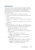 79
79

